
Chapter 7
Aircraft Systems
- When power settings are being decreased, reduce manifold pressure before reducing rpm. If rpm is reduced before manifold pressure, manifold pressure automatically increases, possibly exceeding the manufacturer’s tolerances.
- When power settings are being increased, reverse the order-increase rpm first, then manifold pressure.
- To prevent damage to radial engines, minimize operating time at maximum rpm and manifold pressure, and avoid operation at maximum rpm and low manifold pressure.
The engine and/or airframe manufacturer’s recommendations should be followed to prevent severe wear, fatigue, and damage to high-performance reciprocating engines.
Propeller Overspeed in Piston Engine Aircraft
On March 17, 2010, the Federal Aviation Administration (FAA) issued Special Airworthiness Information Bulletin (SAIB) CE-10-21. The subject was Propellers/Propulsers; Propeller Overspeed in Piston Engine Aircraft to alert operators, pilots, and aircraft manufacturers of concerns for an optimum response to a propeller overspeed in piston engine aircraft with variable pitch propellers. Although a SAIB is not regulatory in nature, the FAA recommends that the information be read and taken into consideration for the safety of flight.
The document explains that a single-engine aircraft experienced a propeller overspeed during cruise flight at 7,000 feet. The pilot reported that the application of throttle resulted in a propeller overspeed with no appreciable thrust. The pilot attempted to glide to a nearby airport and established the “best glide” speed of 110 knots, as published in the Pilot’s Operating Handbook (POH), but was unable to reach the airport and was forced to conduct an off-field landing.
It was further explained that a determination was made that the propeller experienced a failure causing the blade pitch change mechanism to move to the low pitch stop position. This caused the propeller to operate as a fixed-pitch propeller such that it changes rpm with changes in power and airspeed. The low pitch setting allows for maximum power during takeoff but can result in a propeller overspeed at a higher airspeed.
A performance evaluation of the flight condition was performed for the particular aircraft model involved in this incident. This evaluation indicated that an airspeed lower than the best glide speed would have resulted in increased thrust enabling the pilot to maintain level flight. There are numerous variables in aircraft, engines, and propellers that affect aircraft performance. For some aircraft models, the published best glide speed may not be low enough to generate adequate thrust for a given propeller installation in this situation (propeller blades at low pitch stop position).
The operators of aircraft with variable pitch propellers should be aware that in certain instances of propeller overspeed, the airspeed necessary to maintain level flight may be different than the speed associated with engine-out best glide speed. The appropriate emergency procedures should be followed to mitigate the emergency situation in the event of a propeller overspeed; however, pilots should be aware that some reduction in airspeed may result in the ability for continued safe flight and landing. The determination of an airspeed that is more suitable than engine-out best glide speed should only be conducted at a safe altitude when the pilot has time to determine an alternative course of action other than landing immediately.
Induction Systems
The induction system brings in air from the outside, mixes it with fuel, and delivers the fuel-air mixture to the cylinder where combustion occurs. Outside air enters the induction system through an intake port on the front of the engine cowling. This port normally contains an air filter that inhibits the entry of dust and other foreign objects. Since the filter may occasionally become clogged, an alternate source of air must be available. Usually, the alternate air comes from inside the engine cowling, where it bypasses a clogged air filter. Some alternate air sources function automatically, while others operate manually.
Two types of induction systems are commonly used in small aircraft engines:
- The carburetor system mixes the fuel and air in the carburetor before this mixture enters the intake manifold.
- The fuel injection system mixes the fuel and air immediately before entry into each cylinder or injects fuel directly into each cylinder.
Carburetor Systems
Aircraft carburetors are separated into two categories: float-type carburetors and pressure-type carburetors. Float-type carburetors, complete with idling, accelerating, mixture control, idle cutoff, and power enrichment systems, are the most common of the two carburetor types. Pressure-type carburetors are usually not found on small aircraft. The basic difference between a float-type and a pressure-type carburetor is the delivery of fuel. The pressure-type carburetor delivers fuel under pressure by a fuel pump.
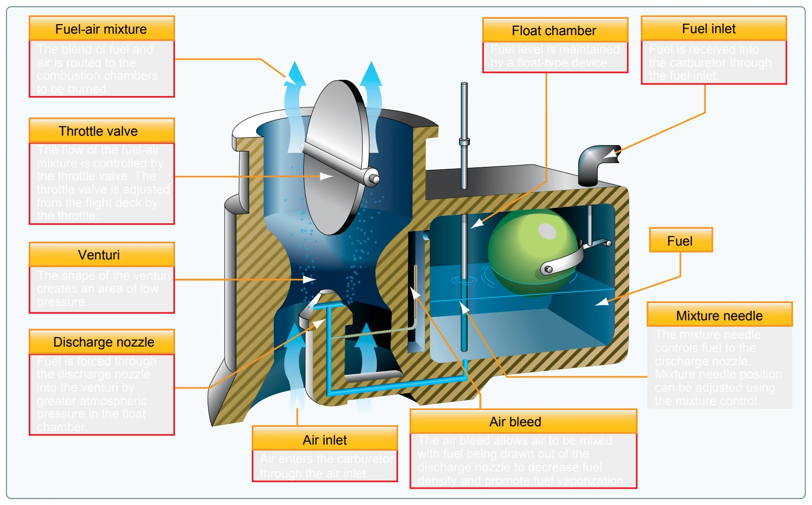
In the operation of the float-type carburetor system, the outside air first flows through an air filter, usually located at an air intake in the front part of the engine cowling. This filtered air flows into the carburetor and through a venturi, a narrow throat in the carburetor. When the air flows through the venturi, a low-pressure area is created that forces the fuel to flow through a main fuel jet located at the throat. The fuel then flows into the airstream where it is mixed with the flowing air. [Figure 7-10]
The fuel-air mixture is then drawn through the intake manifold and into the combustion chambers where it is ignited. The float-type carburetor acquires its name from a float that rests on fuel within the float chamber. A needle attached to the float opens and closes an opening at the bottom of the carburetor bowl. This meters the amount of fuel entering into the carburetor, depending upon the position of the float, which is controlled by the level of fuel in the float chamber. When the level of the fuel forces the float to rise, the needle valve closes the fuel opening and shuts off the fuel flow to the carburetor. The needle valve opens again when the engine requires additional fuel. The flow of the fuel-air mixture to the combustion chambers is regulated by the throttle valve, which is controlled by the throttle in the flight deck.
The float-type carburetor has several distinct disadvantages. First, they do not function well during abrupt maneuvers. Secondly, the discharge of fuel at low pressure leads to incomplete vaporization and difficulty in discharging fuel into some types of supercharged systems. The chief disadvantage of the float-type carburetor, however, is its icing tendency. Since the float-type carburetor must discharge
fuel at a point of low pressure, the discharge nozzle must be located at the venturi throat, and the throttle valve must be on the engine side of the discharge nozzle. This means that the drop in temperature due to fuel vaporization takes place within the venturi. As a result, ice readily forms in the venturi and on the throttle valve.
A pressure-type carburetor discharges fuel into the airstream at a pressure well above atmospheric pressure. This results in better vaporization and permits the discharge of fuel into the airstream on the engine side of the throttle valve. With the discharge nozzle in this position fuel vaporization takes place after the air has passed through the throttle valve and at a point where the drop in temperature is offset by heat from the engine. Thus, the danger of fuel vaporization icing is practically eliminated. The effects of rapid maneuvers and rough air on the pressure-type carburetors are negligible, since their fuel chambers remain filled under all operating conditions.