
Chapter 7
Aircraft Systems
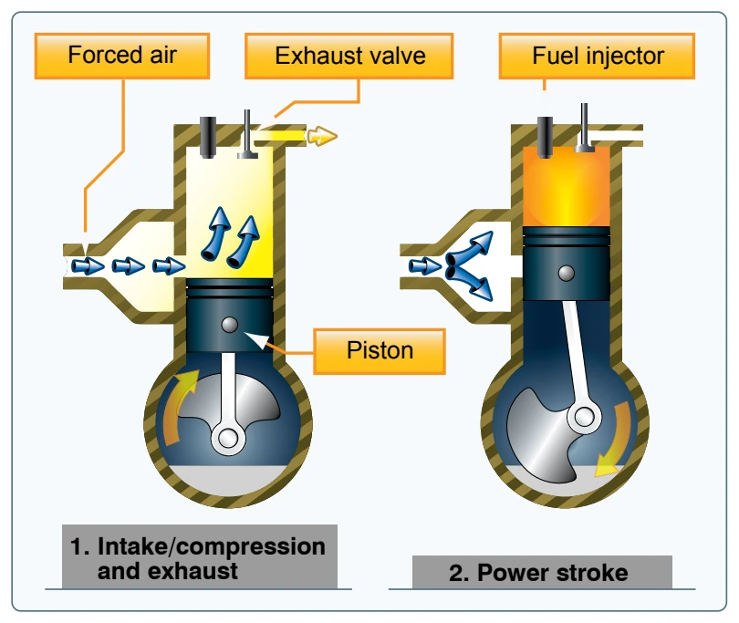
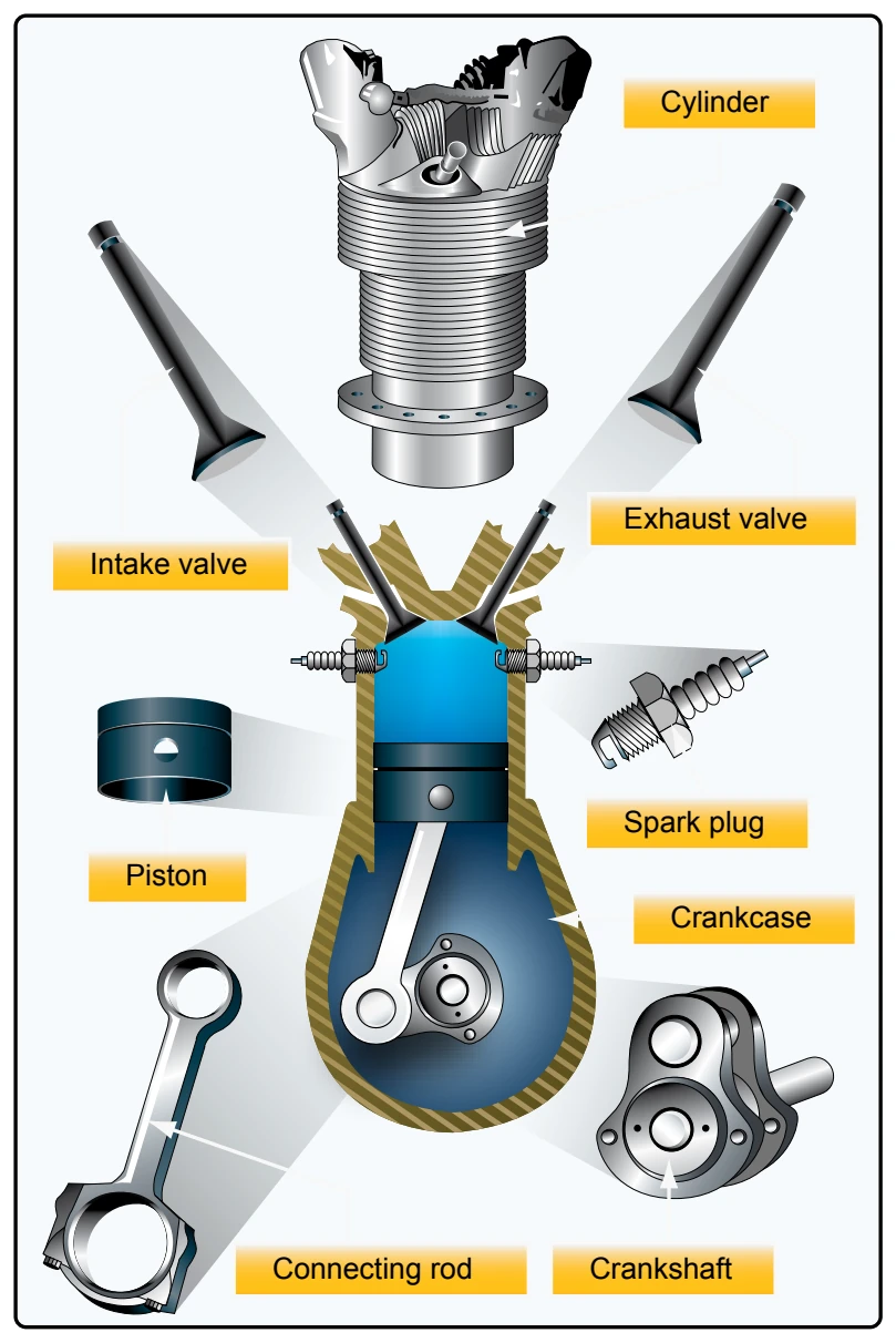
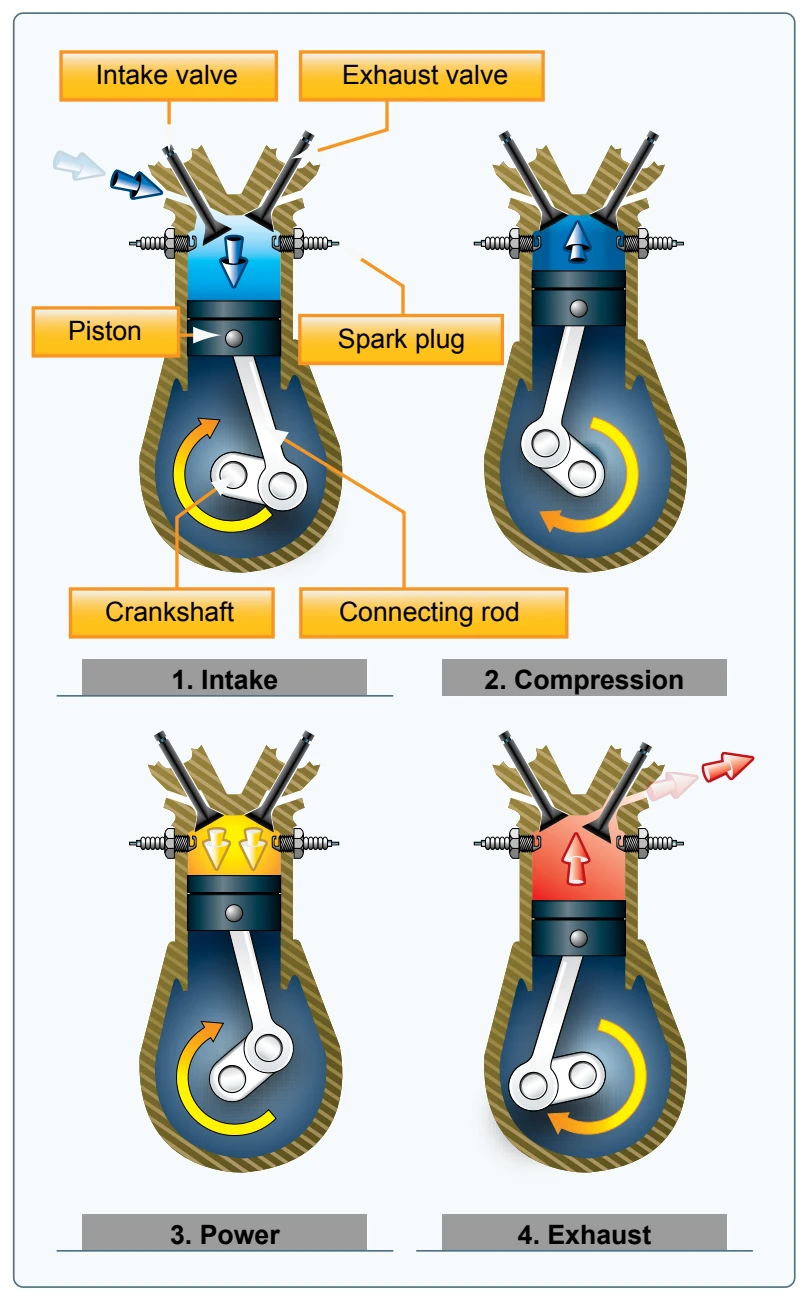
In a four-stroke engine, the conversion of chemical energy into mechanical energy occurs over a four-stroke operating cycle. The intake, compression, power, and exhaust processes occur in four separate strokes of the piston in the following order.
- The intake stroke begins as the piston starts its downward travel. When this happens, the intake valve opens and the fuel-air mixture is drawn into the cylinder.
- The compression stroke begins when the intake valve closes, and the piston starts moving back to the top of the cylinder. This phase of the cycle is used to obtain a much greater power output from the fuel-air mixture once it is ignited.
- The power stroke begins when the fuel-air mixture is ignited. This causes a tremendous pressure increase in the cylinder and forces the piston downward away from the cylinder head, creating the power that turns the crankshaft.
- The exhaust stroke is used to purge the cylinder of burned gases. It begins when the exhaust valve opens, and the piston starts to move toward the cylinder head once again.
Even when the engine is operated at a fairly low speed, the four-stroke cycle takes place several hundred times each minute. [Figure 7-5] In a four-cylinder engine, each cylinder operates on a different stroke. Continuous rotation of a crankshaft is maintained by the precise timing of the power strokes in each cylinder. Continuous operation of the engine depends on the simultaneous function of auxiliary systems, including the induction, ignition, fuel, oil, cooling, and exhaust systems.
The latest advance in aircraft reciprocating engines was pioneered in the mid-1960s by Frank Thielert, who looked to the automotive industry for answers on how to integrate diesel technology into an aircraft engine. The advantage
of a diesel-fueled reciprocating engine lies in the physical similarity of diesel and kerosene. Aircraft equipped with a diesel piston engine runs on standard aviation fuel kerosene, which provides more independence, higher reliability, lower consumption, and operational cost saving.
In 1999, Thielert formed Thielert Aircraft Engines (TAE) to design, develop, certify, and manufacture a brand-new Jet-A-burning diesel cycle engine (also known as jet-fueled piston engine) for the GA industry. By March 2001, the first prototype engine became the first certified diesel engine since World War II. TAE continues to design and develop diesel cycle engines and other engine manufacturers, such as Société de Motorisations Aéronautiques (SMA), now offer jet-fueled piston engines as well. TAE engines can be found on the Diamond DA40 single and the DA42 Twin Star; the first diesel engine to be part of the type certificate of a new original equipment manufacturer (OEM) aircraft.
These engines have also gained a toehold in the retrofit market with a supplemental type certificate (STC) to re-engine the Cessna 172 models and the Piper PA-28 family. The jet-fueled piston engine’s technology has continued to progress and a full authority digital engine control (FADEC, discussed more fully later in the chapter) is standard on such equipped aircraft, which minimizes complication of engine control. By 2007, various jet-fueled piston aircraft had logged well over 600,000 hours of service.
Propeller
The propeller is a rotating airfoil, subject to induced drag, stalls, and other aerodynamic principles that apply to any airfoil. It provides the necessary thrust to pull, or in some cases push, the aircraft through the air. The engine power is used to rotate the propeller, which in turn generates thrust very similar to the manner in which a wing produces lift. The amount of thrust produced depends on the shape of the airfoil, the angle of attack (AOA) of the propeller blade, and the revolutions per minute (rpm) of the engine. The propeller itself is twisted so the blade angle changes from hub to tip. The greatest angle of incidence, or the highest pitch, is at the hub while the smallest angle of incidence or smallest pitch is at the tip. [Figure 7-6]
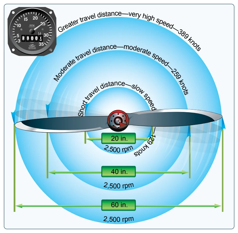
The reason for the twist is to produce uniform lift from the hub to the tip. As the blade rotates, there is a difference in the actual speed of the various portions of the blade. The tip of the blade travels faster than the part near the hub, because the tip travels a greater distance than the hub in the same length of time. [Figure 7-7] Changing the angle of incidence (pitch) from the hub to the tip to correspond with the speed produces uniform lift throughout the length of the blade. A propeller blade designed with the same angle of incidence
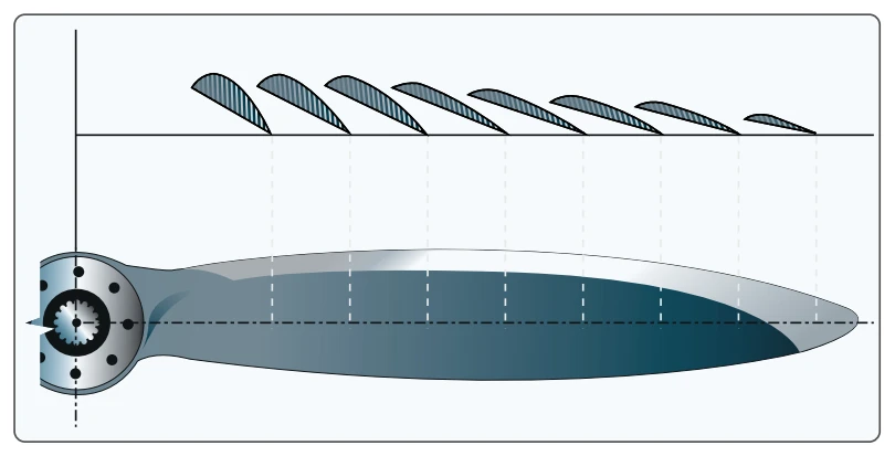
throughout its entire length would be inefficient because as airspeed increases in flight, the portion near the hub would have a negative AOA while the blade tip would be stalled. Small aircraft are equipped with either one of two types of propellers: fixed-pitch or adjustable-pitch.
Fixed-Pitch Propeller
A propeller with fixed blade angles is a fixed-pitch propeller. The pitch of this propeller is set by the manufacturer and cannot be changed. Since a fixed-pitch propeller achieves the best efficiency only at a given combination of airspeed and rpm, the pitch setting is ideal for neither cruise nor climb. Thus, the aircraft suffers a bit in each performance category. The fixed-pitch propeller is used when low weight, simplicity, and low cost are needed.
There are two types of fixed-pitch propellers: climb and cruise. Whether the airplane has a climb or cruise propeller
installed depends upon its intended use. The climb propeller has a lower pitch, therefore less drag. Less drag results in higher rpm and more horsepower capability, which increases performance during takeoffs and climbs but decreases performance during cruising flight.