
Chapter 6
Flight Controls
Introduction
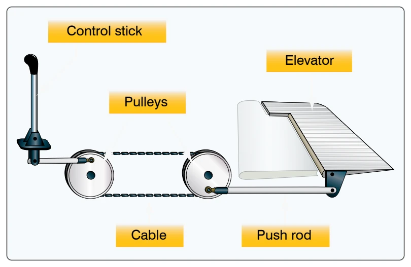
This chapter focuses on the flight control systems a pilot uses to control the forces of flight and the aircraft’s direction and attitude. It should be noted that flight control systems and characteristics can vary greatly depending on the type of aircraft flown. The most basic flight control system designs are mechanical and date back to early aircraft. They operate with a collection of mechanical parts, such as rods, cables, pulleys, and sometimes chains to transmit the forces of the flight deck controls to the control surfaces. Mechanical flight control systems are still used today in small general and sport category aircraft where the aerodynamic forces are not excessive. [Figure 6-1]
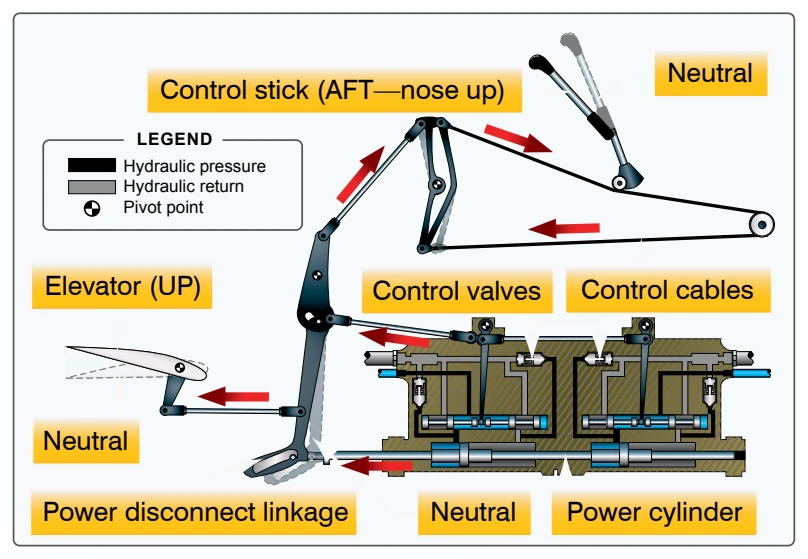
As aviation matured and aircraft designers learned more about aerodynamics, the industry produced larger and faster aircraft. Therefore, the aerodynamic forces acting upon the control surfaces increased exponentially. To make the control force required by pilots manageable, aircraft engineers designed more complex systems. At first, hydromechanical designs, consisting of a mechanical circuit and a hydraulic circuit, were used to reduce the complexity, weight, and limitations of mechanical flight controls systems. [Figure 6-2]
As aircraft became more sophisticated, the control surfaces were actuated by electric motors, digital computers, or fiber optic cables. Called “fly-by-wire,” this flight control system replaces the physical connection between pilot controls and the flight control surfaces with an electrical interface. In addition, in some large and fast aircraft, controls are boosted by hydraulically or electrically actuated systems. In both the fly-by-wire and boosted controls, the feel of the control reaction is fed back to the pilot by simulated means.
Current research at the National Aeronautics and Space Administration (NASA) Dryden Flight Research Center involves Intelligent Flight Control Systems (IFCS). The goal
of this project is to develop an adaptive neural network-based flight control system. Applied directly to flight control system feedback errors, IFCS provides adjustments to improve aircraft performance in normal flight, as well as with system failures. With IFCS, a pilot is able to maintain control and safely land an aircraft that has suffered a failure to a control surface or damage to the airframe. It also improves mission capability, increases the reliability and safety of flight, and eases the pilot workload.
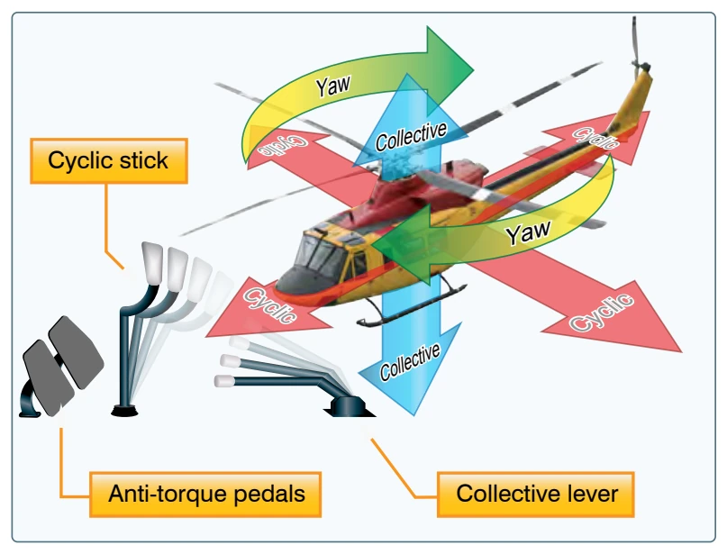
Today’s aircraft employ a variety of flight control systems. For example, some aircraft in the sport pilot category rely on weight-shift control to fly while balloons use a standard burn technique. Helicopters utilize a cyclic to tilt the rotor in the desired direction along with a collective to manipulate rotor pitch and anti-torque pedals to control yaw. [Figure 6-3]
For additional information on flight control systems, refer to the appropriate handbook for information related to the flight control systems and characteristics of specific types of aircraft.
Flight Control Systems
Flight Controls
Aircraft flight control systems consist of primary and secondary systems. The ailerons, elevator (or stabilator), and rudder constitute the primary control system and are required to control an aircraft safely during flight. Wing flaps, leading edge devices, spoilers, and trim systems constitute the secondary control system and improve the performance characteristics of the airplane or relieve the pilot of excessive control forces.
Primary Flight Controls
Aircraft control systems are carefully designed to provide adequate responsiveness to control inputs while allowing a
natural feel. At low airspeeds, the controls usually feel soft and sluggish, and the aircraft responds slowly to control applications. At higher airspeeds, the controls become increasingly firm and aircraft response is more rapid.
Movement of any of the three primary flight control surfaces (ailerons, elevator or stabilator, or rudder), changes the airflow and pressure distribution over and around the airfoil. These changes affect the lift and drag produced by the airfoil/ control surface combination, and allow a pilot to control the aircraft about its three axes of rotation.
Design features limit the amount of deflection of flight control surfaces. For example, control-stop mechanisms may be incorporated into the flight control linkages, or movement of the control column and/or rudder pedals may be limited. The purpose of these design limits is to prevent the pilot from inadvertently overcontrolling and overstressing the aircraft during normal maneuvers.
A properly designed aircraft is stable and easily controlled during normal maneuvering. Control surface inputs cause movement about the three axes of rotation. The types of stability an aircraft exhibits also relate to the three axes of rotation. [Figure 6-4]