
Chapter 7
Aircraft Systems
The points where the aircraft drag curve intersects the net thrust curves are the maximum aircraft speeds. The vertical lines from each of the points to the baseline of the graph indicate that the turbojet aircraft can attain a higher maximum speed than aircraft equipped with the other types of engines. Aircraft equipped with the turbofan engine attains a higher maximum speed than aircraft equipped with a turboprop or reciprocating powerplant.
Airframe Systems
Fuel, electrical, hydraulic, and oxygen systems make up the airframe systems.
Fuel Systems
The fuel system is designed to provide an uninterrupted flow of clean fuel from the fuel tanks to the engine. The fuel must be available to the engine under all conditions of engine power, altitude, attitude, and during all approved flight maneuvers. Two common classifications apply to fuel systems in small aircraft: gravity-feed and fuel-pump systems.
Gravity-Feed System
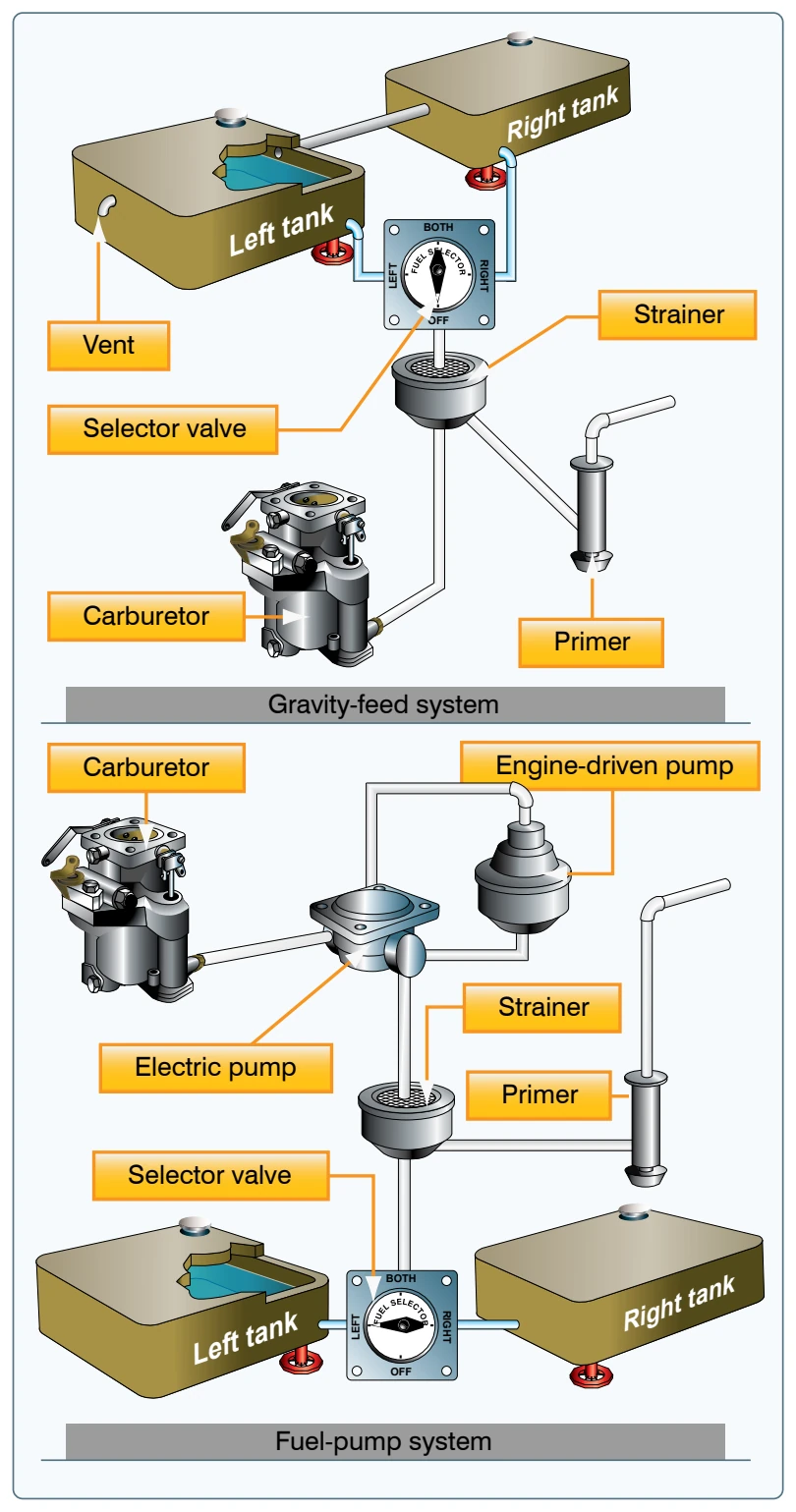
The gravity-feed system utilizes the force of gravity to transfer the fuel from the tanks to the engine. For example, on high-wing airplanes, the fuel tanks are installed in the wings. This places the fuel tanks above the carburetor, and the fuel is gravity fed through the system and into the carburetor. If the design of the aircraft is such that gravity cannot be used to transfer fuel, fuel pumps are installed. For example, on low-wing airplanes, the fuel tanks in the wings are located below the carburetor. [Figure 7-30]
Fuel-Pump System
Aircraft with fuel-pump systems have two fuel pumps. The main pump system is engine driven with an electrically-driven auxiliary pump provided for use in engine starting and in the event the engine pump fails. The auxiliary pump, also known as a boost pump, provides added reliability to the fuel system. The electrically-driven auxiliary pump is controlled by a switch in the flight deck.
Fuel Primer
Both gravity-feed and fuel-pump systems may incorporate a fuel primer into the system. The fuel primer is used to draw fuel from the tanks to vaporize fuel directly into the cylinders prior to starting the engine. During cold weather, when engines are difficult to start, the fuel primer helps because there is not enough heat available to vaporize the fuel in the carburetor. It is important to lock the primer in place when it is not in use. If the knob is free to move, it may vibrate out of position during flight which may cause an excessively rich fuel-air mixture. To avoid overpriming, read the priming instructions for the aircraft.
Fuel Tanks
The fuel tanks, normally located inside the wings of an airplane, have a filler opening on top of the wing through which they can be filled. A filler cap covers this opening.
The tanks are vented to the outside to maintain atmospheric pressure inside the tank. They may be vented through the filler cap or through a tube extending through the surface of the wing. Fuel tanks also include an overflow drain that may stand alone or be collocated with the fuel tank vent. This allows fuel to expand with increases in temperature without damage to the tank itself. If the tanks have been filled on a hot day, it is not unusual to see fuel coming from the overflow drain.
Fuel Gauges
The fuel quantity gauges indicate the amount of fuel measured by a sensing unit in each fuel tank and is displayed in gallons or pounds. Aircraft certification rules require accuracy in fuel gauges only when they read “empty.” Any reading other than “empty” should be verified. Do not depend solely on the accuracy of the fuel quantity gauges. Always visually check the fuel level in each tank during the preflight inspection, and then compare it with the corresponding fuel quantity indication.
If a fuel pump is installed in the fuel system, a fuel pressure gauge is also included. This gauge indicates the pressure in the fuel lines. The normal operating pressure can be found in the AFM/POH or on the gauge by color coding.
Fuel Selectors
The fuel selector valve allows selection of fuel from various tanks. A common type of selector valve contains four positions: LEFT, RIGHT, BOTH, and OFF. Selecting the LEFT or RIGHT position allows fuel to feed only from the respective tank, while selecting the BOTH position feeds fuel from both tanks. The LEFT or RIGHT position may be used to balance the amount of fuel remaining in each wing tank. [Figure 7-31]