
Chapter 5
Aerodynamics of Flight
In order for ground effect to be of significant magnitude, the wing must be quite close to the ground. One of the direct results of ground effect is the variation of induced drag with wing height above the ground at a constant CL. When the wing is at a height equal to its span, the reduction in induced drag is only 1.4 percent. However, when the wing is at a height equal to one-fourth its span, the reduction in induced drag is 23.5 percent and, when the wing is at a height equal to one-tenth its span, the reduction in induced drag is 47.6 percent. Thus, a large reduction in induced drag takes place only when the wing is very close to the ground. Because of this variation, ground effect is most usually recognized during the liftoff for takeoff or just prior to touchdown when landing.
During the takeoff phase of flight, ground effect produces some important relationships. An aircraft leaving ground effect after takeoff encounters just the reverse of an aircraft entering ground effect during landing. The aircraft leaving ground effect will:
- Require an increase in AOA to maintain the same CL
- Experience an increase in induced drag and thrust required
- Experience a decrease in stability and a nose-up change in moment
- Experience a reduction in static source pressure and increase in indicated airspeed
Ground effect must be considered during takeoffs and landings. For example, if a pilot fails to understand the relationship between the aircraft and ground effect during takeoff, a hazardous situation is possible because the recommended takeoff speed may not be achieved. Due to the reduced drag in ground effect, the aircraft may seem capable of takeoff well below the recommended speed. As the aircraft rises out of ground effect with a deficiency of speed, the greater induced drag may result in marginal initial climb performance. In extreme conditions, such as high gross weight, high density altitude, and high temperature, a deficiency of airspeed during takeoff may permit the aircraft to become airborne but be incapable of sustaining flight out of ground effect. In this case, the aircraft may become airborne initially with a deficiency of speed and then settle back to the runway.
A pilot should not attempt to force an aircraft to become airborne with a deficiency of speed. The manufacturer’s recommended takeoff speed is necessary to provide adequate initial climb performance. It is also important that a definite climb be established before a pilot retracts the landing gear or flaps. Never retract the landing gear or flaps prior to establishing a positive rate of climb and only after achieving a safe altitude.
If, during the landing phase of flight, the aircraft is brought into ground effect with a constant AOA, the aircraft experiences an increase in CL and a reduction in the thrust required, and a “floating” effect may occur. Because of the reduced drag and lack of power-off deceleration in ground effect, any excess speed at the point of flare may incur a considerable “float” distance. As the aircraft nears the point of touchdown, ground effect is most realized at altitudes less than the wingspan. During the final phases of the approach as the aircraft nears the ground, a reduction of power is necessary to offset the increase in lift caused from ground effect otherwise the aircraft will have a tendency to climb above the desired glidepath (GP).
Axes of an Aircraft
The axes of an aircraft are three imaginary lines that pass through an aircraft’s CG. The axes can be considered as imaginary axles around which the aircraft turns. The three axes pass through the CG at 90° angles to each other. The axis passes through the CG and parallel to a line from nose to tail is the longitudinal axis, the axis that passes parallel to a line from wingtip to wingtip is the lateral axis, and the axis that passes through the CG at right angles to the other two axes is the vertical axis. Whenever an aircraft changes its flight attitude or position in flight, it rotates about one or more of the three axes. [Figure 5-18]
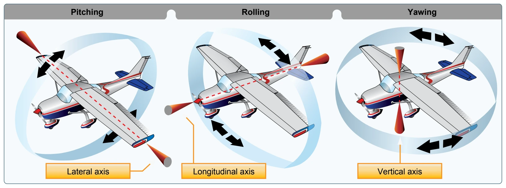
The aircraft’s motion about its longitudinal axis resembles the roll of a ship from side to side. In fact, the names used to describe the motion about an aircraft’s three axes were originally nautical terms. They have been adapted to aeronautical terminology due to the similarity of motion of aircraft and seagoing ships. The motion about the aircraft’s longitudinal axis is “roll,” the motion about its lateral axis is “pitch,” and the motion about its vertical axis is “yaw.” Yaw is the left and right movement of the aircraft’s nose.
The three motions of the conventional airplane (roll, pitch, and yaw) are controlled by three control surfaces. Roll is controlled by the ailerons; pitch is controlled by the elevators; yaw is controlled by the rudder. The use of these controls is explained in Chapter 6, Flight Controls. Other types of aircraft may utilize different methods of controlling the movements about the various axes.
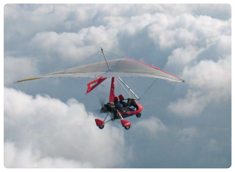
For example, weight-shift control aircraft control two axes (roll and pitch) using an “A” frame suspended from the flexible wing attached to a three-wheeled carriage. These aircraft are controlled by moving a horizontal bar (called a control bar) in roughly the same way hang glider pilots fly. [Figure 5-19] They are termed weight-shift control aircraft because the pilot controls the aircraft by shifting the CG. For more information on weight-shift control aircraft, see the Federal Aviation Administration (FAA) Weight-Shift Control Flying Handbook, FAA-H-8083-5. In the case of powered parachutes, aircraft control is accomplished by altering the airfoil via steering lines.
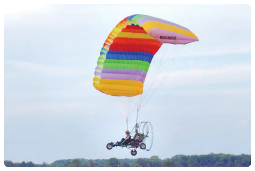
A powered parachute wing is a parachute that has a cambered upper surface and a flatter under surface. The two surfaces are separated by ribs that act as cells, which open to the airflow at the leading edge and have internal ports to allow lateral airflow. The principle at work holds that the cell pressure is greater than the outside pressure, thereby forming a wing that maintains its airfoil shape in flight. The pilot and passenger sit in tandem in front of the engine, which is located at the rear of a vehicle. The airframe is attached to the parachute via two attachment points and lines. Control is accomplished by both power and the changing of the airfoil via the control lines. [Figure 5-20]
Moment and Moment Arm
A study of physics shows that a body that is free to rotate will always turn about its CG. In aerodynamic terms, the mathematical measure of an aircraft’s tendency to rotate about its CG is called a “moment.” A moment is said to be equal to the product of the force applied and the distance at which the force is applied. (A moment arm is the distance from a datum [reference point or line] to the applied force.) For aircraft weight and balance computations, “moments” are expressed in terms of the distance of the arm times the aircraft’s weight, or simply, inch-pounds.
Aircraft designers locate the fore and aft position of the aircraft’s CG as nearly as possible to the 20 percent point of the mean aerodynamic chord (MAC). If the thrust line is designed to pass horizontally through the CG, it will not cause the aircraft to pitch when power is changed, and there will be no difference in moment due to thrust for a power-on or power-off condition of flight. Although designers have some control over the location of the drag forces, they are not always able to make the resultant drag forces pass through the CG of the aircraft. However, the one item over which they have the greatest control is the size and location of the tail. The objective is to make the moments (due to thrust, drag, and lift) as small as possible and, by proper location of the tail, to provide the means of balancing an aircraft longitudinally for any condition of flight.
The pilot has no direct control over the location of forces acting on the aircraft in flight, except for controlling the center of lift by changing the AOA. The pilot can control the magnitude of the forces. Such a change, however, immediately involves changes in other forces. Therefore, the pilot cannot independently change the location of one force without changing the effect of others. For example, a change in airspeed involves a change in lift, as well as a change in drag and a change in the up or down force on the tail. As forces such as turbulence and gusts act to displace the aircraft, the pilot reacts by providing opposing control forces to counteract this displacement.
Some aircraft are subject to changes in the location of the CG with variations of load. Trimming devices, such as elevator trim tabs and adjustable horizontal stabilizers, are used to counteract the moments set up by fuel burnoff and loading or off-loading of passengers or cargo.