
Chapter 5
Aerodynamics of Flight
The airflow outside of the boundary layer reacts to the shape of the edge of the boundary layer just as it would to the physical surface of an object. The boundary layer gives any object an “effective” shape that is usually slightly different from the physical shape. The boundary layer may also separate from the body, thus creating an effective shape much different from the physical shape of the object. This change in the physical shape of the boundary layer causes a dramatic decrease in lift and an increase in drag. When this happens, the airfoil has stalled.
In order to reduce the effect of skin friction drag, aircraft designers utilize flush mount rivets and remove any irregularities that may protrude above the wing surface. In addition, a smooth and glossy finish aids in transition of air across the surface of the wing. Since dirt on an aircraft disrupts the free flow of air and increases drag, keep the surfaces of an aircraft clean and waxed.
Induced Drag
The second basic type of drag is induced drag. It is an established physical fact that no system that does work in the mechanical sense can be 100 percent efficient. This means that whatever the nature of the system, the required work is obtained at the expense of certain additional work that is dissipated or lost in the system. The more efficient the system, the smaller this loss.
In level flight, the aerodynamic properties of a wing or rotor produce a required lift, but this can be obtained only at the expense of a certain penalty. The name given to this penalty is induced drag. Induced drag is inherent whenever an airfoil is producing lift and, in fact, this type of drag is inseparable from the production of lift. Consequently, it is always present if lift is produced.
An airfoil (wing or rotor blade) produces the lift force by making use of the energy of the free airstream. Whenever an airfoil is producing lift, the pressure on the lower surface of it is greater than that on the upper surface (Bernoulli’s Principle). As a result, the air tends to flow from the high pressure area below the tip upward to the low pressure area on the upper surface. In the vicinity of the tips, there is a tendency for these pressures to equalize, resulting in a lateral flow outward from the underside to the upper surface. This lateral flow imparts a rotational velocity to the air at the tips, creating vortices that trail behind the airfoil.
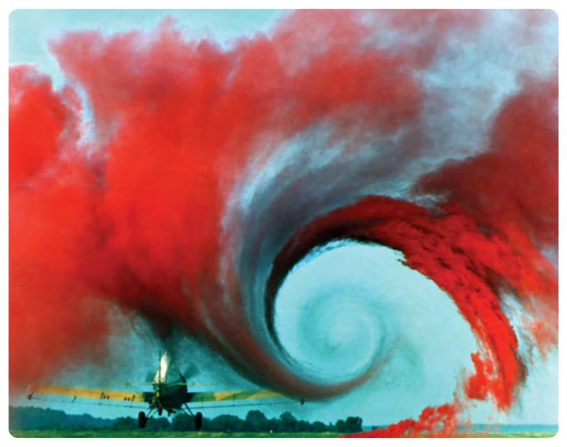
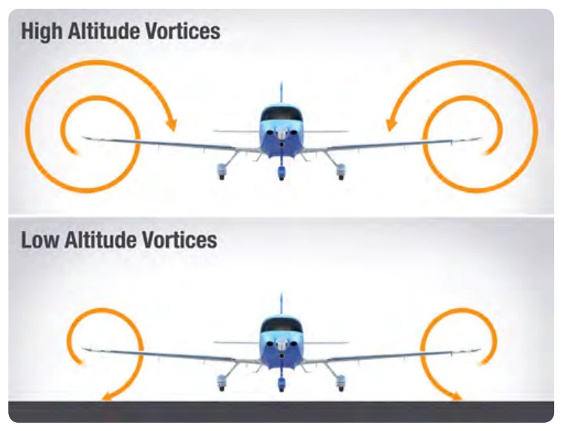
When the aircraft is viewed from the tail, these vortices circulate counterclockwise about the right tip and clockwise about the left tip. [Figure 5-9] As the air (and vortices) roll off the back of your wing, they angle down, which is known as downwash. Figure 5-10 shows the difference in downwash at altitude versus near the ground. Bearing in mind the direction of rotation of these vortices, it can be seen that they induce an upward flow of air beyond the tip and a downwash flow behind the wing’s trailing edge. This induced downwash has nothing in common with the downwash that is necessary to produce lift. It is, in fact, the source of induced drag.
Downwash points the relative wind downward, so the more downwash you have, the more your relative wind points downward. That's important for one very good reason: lift is always perpendicular to the relative wind. In Figure 5-11, you can see that when you have less downwash, your lift vector is more vertical, opposing gravity. And when you have more downwash, your lift vector points back more, causing induced drag. On top of that, it takes energy for your wings to create downwash and vortices, and that energy creates drag.
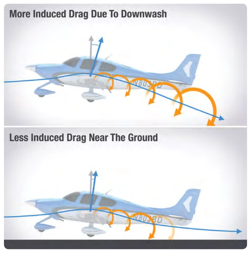
The greater the size and strength of the vortices and consequent downwash component on the net airflow over the airfoil, the greater the induced drag effect becomes. This downwash over the top of the airfoil at the tip has the same effect as bending the lift vector rearward; therefore, the lift is slightly aft of perpendicular to the relative wind, creating a rearward lift component. This is induced drag.
In order to create a greater negative pressure on the top of an airfoil, the airfoil can be inclined to a higher AOA. If the AOA of a symmetrical airfoil were zero, there would be no pressure differential, and consequently, no downwash component and no induced drag. In any case, as AOA increases, induced drag increases proportionally. To state this another way—the lower the airspeed, the greater the AOA required to produce lift equal to the aircraft’s weight and, therefore, the greater induced drag. The amount of induced drag varies inversely with the square of the airspeed.
Conversely, parasite drag increases as the square of the airspeed. Thus, in steady state, as airspeed decreases to near the stalling speed, the total drag becomes greater, due mainly to the sharp rise in induced drag. Similarly, as the aircraft reaches its never-exceed speed (VNE), the total drag increases rapidly due to the sharp increase of parasite drag. As seen in Figure 5-6, at some given airspeed, total drag is at its minimum amount. In figuring the maximum range of aircraft, the thrust required to overcome drag is at a minimum if drag is at a minimum. The minimum power and maximum endurance occur at a different point.
Weight
Gravity is the pulling force that tends to draw all bodies to the center of the earth. The CG may be considered as a point at which all the weight of the aircraft is concentrated. If the aircraft were supported at its exact CG, it would balance in any attitude. It will be noted that CG is of major importance in an aircraft, for its position has a great bearing upon stability. The allowable location of the CG is determined by the general design of each particular aircraft. The designers determine how far the center of pressure (CP) will travel. It is important to understand that an aircraft’s weight is concentrated at the CG and the aerodynamic forces of lift occur at the CP. When the CG is forward of the CP, there is a natural tendency for the aircraft to want to pitch nose down. If the CP is forward of the CG, a nose up pitching moment is created. Therefore, designers fix the aft limit of the CG forward of the CP for the corresponding flight speed in order to retain flight equilibrium.
Weight has a definite relationship to lift. This relationship is simple, but important in understanding the aerodynamics of flying. Lift is the upward force on the wing acting perpendicular to the relative wind and perpendicular to the aircraft’s lateral axis. Lift is required to counteract the aircraft’s weight. In stabilized level flight, when the lift force is equal to the weight force, the aircraft is in a state of equilibrium and neither accelerates upward or downward. If lift becomes less than weight, the vertical speed will decrease. When lift is greater than weight, the vertical speed will increase.
Wingtip Vortices
Formation of Vortices
The action of the airfoil that gives an aircraft lift also causes induced drag. When an airfoil is flown at a positive AOA, a pressure differential exists between the upper and lower surfaces of the airfoil. The pressure above the wing is less than atmospheric pressure and the pressure below the wing is equal to or greater than atmospheric pressure. Since air always moves from high pressure toward low pressure, and the path of least resistance is toward the airfoil’s tips, there is a spanwise movement of air from the bottom of the airfoil outward from the fuselage around the tips. This flow of air results in “spillage” over the tips, thereby setting up a whirlpool of air called a vortex. [Figure 5-12]