
Chapter 16
Navigation
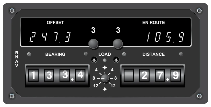
difficult to measure to that level of accuracy, and in practical application, it is rarely necessary. A number of flight planning publications publish airport coordinates and waypoints with this precision and the unit accepts those figures. There is a subtle but important difference in CDI operation and display in the RNAV modes.
In the RNAV modes, course deviation is displayed in terms of linear deviation. In the RNAV en route mode, maximum deflection of the CDI typically represents 5 NM on either side of the selected course without regard to distance from the waypoint. In the RNAV approach mode, maximum deflection of the CDI typically represents 1¼ NM on either side of the selected course. There is no increase in CDI sensitivity as the aircraft approaches a waypoint in RNAV mode.
The RNAV approach mode is used for instrument approaches. Its narrow scale width (¼ of the en route mode) permits very precise tracking to or from the selected waypoint. In VFR cross-country navigation, tracking a course in the approach mode is not desirable because it requires a great deal of attention and soon becomes tedious.
A fourth, lesser-used mode on some units is the VOR Parallel mode. This permits the CDI to display linear (not angular) deviation as the aircraft tracks to and from VORTACs. It derives its name from permitting the pilot to offset (or parallel) a selected course or airway at a fixed distance of the pilot’s choosing, if desired. The VOR parallel mode has the same effect as placing a waypoint directly over an existing VORTAC. Some pilots select the VOR parallel mode when utilizing the navigation (NAV) tracking function of their autopilot for smoother course following near the VORTAC.
Navigating an aircraft with VOR/DME-based RNAV can be confusing, and it is essential that the pilot become familiar with the equipment installed. It is not unknown for pilots to operate inadvertently in one of the RNAV modes when the operation was not intended, by overlooking switch positions or annunciators. The reverse has also occurred with a pilot neglecting to place the unit into one of the RNAV modes by overlooking switch positions or annunciators. As always, the prudent pilot is not only familiar with the equipment used, but never places complete reliance in just one method of navigation when others are available for cross-check.
Automatic Direction Finder (ADF)
Many general aviation-type aircraft are equipped with ADF radio receiving equipment. To navigate using the ADF, the pilot tunes the receiving equipment to a ground station known as a nondirectional radio beacon (NDB). The NDB stations normally operate in a low or medium frequency band of 200 to 415 kHz. The frequencies are readily available on aeronautical charts or in the Chart Supplement U.S.
All radio beacons, except compass locators, transmit a continuous three-letter identification in code, except during voice transmissions. A compass locator, which is associated with an instrument landing system, transmits a two-letter identification.
Standard broadcast stations can also be used in conjunction with ADF. Positive identification of all radio stations is extremely important and this is particularly true when using standard broadcast stations for navigation.
NDBs have one advantage over the VOR in that low or medium frequencies are not affected by line-of-sight. The signals follow the curvature of the Earth; therefore, if the aircraft is within the range of the station, the signals can be received regardless of altitude.
The following table gives the class of NDB stations, their power, and their usable range:
NONDIRECTIONAL RADIO BEACON (NDB) (Usable radius distances for all altitudes)
Class (Watts) (Miles) Compass Locator Under 25 15 MH Under 50 25 H 50-1999 *50 HH 2000 or more 75
*Service range of individual facilities may be less than 50 miles.
One of the disadvantages that should be considered when using low frequency (LF) for navigation is that LF signals are very susceptible to electrical disturbances, such as lightning. These disturbances create excessive static, needle deviations, and signal fades. There may be interference from distant stations. Pilots should know the conditions under which these disturbances can occur so they can be more alert to possible interference when using the ADF.
Basically, the ADF aircraft equipment consists of a tuner, which is used to set the desired station frequency, and the navigational display.
The navigational display consists of a dial upon which the azimuth is printed and a needle which rotates around the dial and points to the station to which the receiver is tuned.
Some of the ADF dials can be rotated to align the azimuth with the aircraft heading; others are fixed with 0° representing the nose of the aircraft and 180° representing the tail. Only the fixed azimuth dial is discussed in this handbook. [Figure 16-37]
and should be understood by the pilot.