
Chapter 8
Flight Instruments
The slip/skid indicator is the horizontal line below the roll pointer. [Figure 8-12] Like a ball in a turn-and-slip indicator, a bar width off center is equal to one ball width displacement.
Turn Rate Indicator
The turn rate indicator, illustrated in Figure 8-12, is typically found directly above the rotating compass card. Tick marks to the left and right of the lubber line denote the turn (standard-rate versus half standard-rate). Typically denoted by a trend line, if the trend vector is extended to the second tick mark the aircraft is in a standard-rate turn.
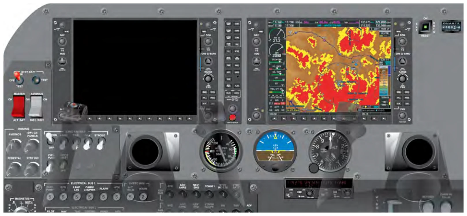
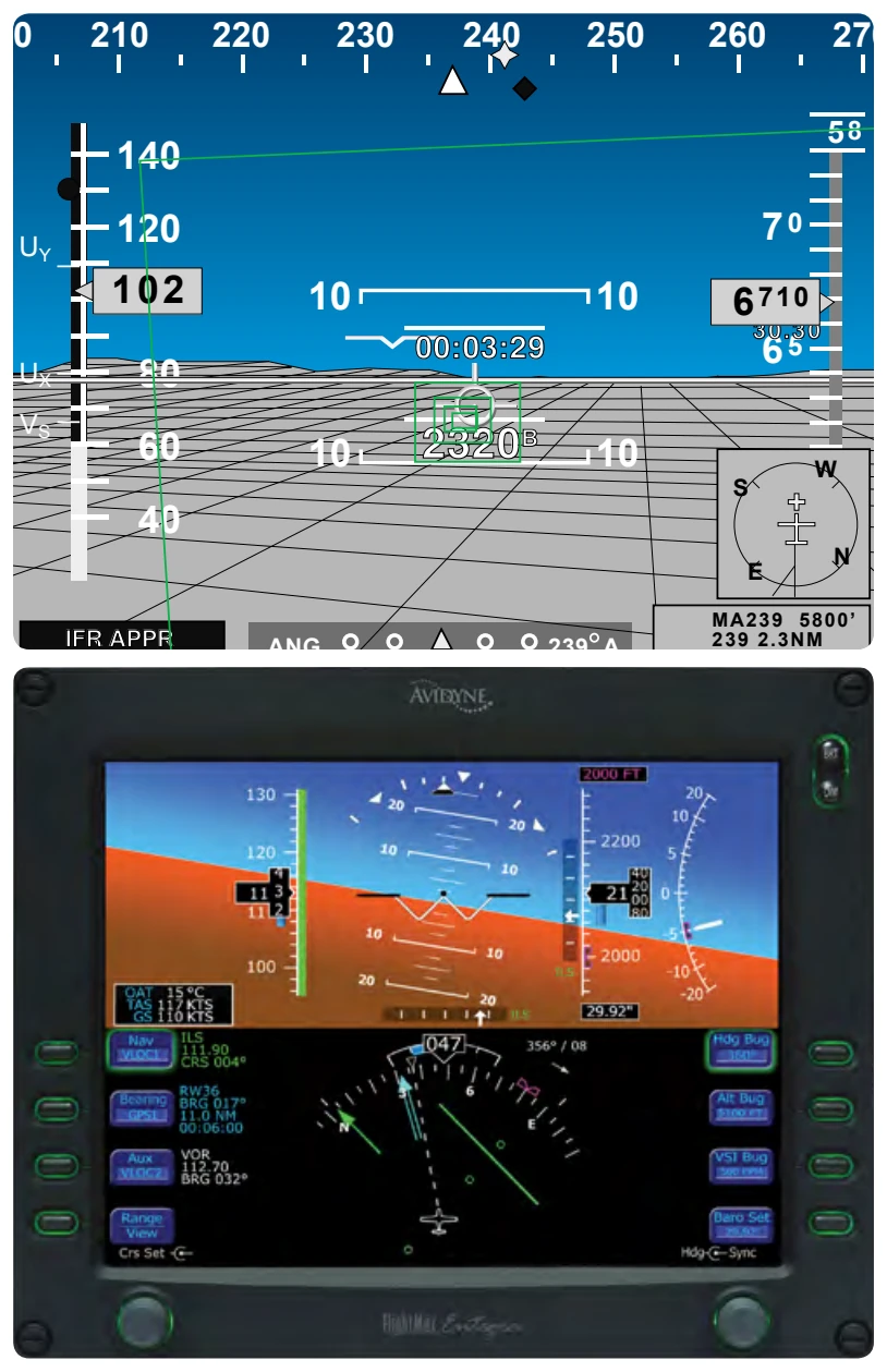
Individual panel displays can be configured for a variety of aircraft by installing different software packages. [Figure 8-14] Manufacturers are also able to upgrade existing instrument displays in a similar manner, eliminating the need to replace individual gauges in order to upgrade.
Air Data Computer (ADC)
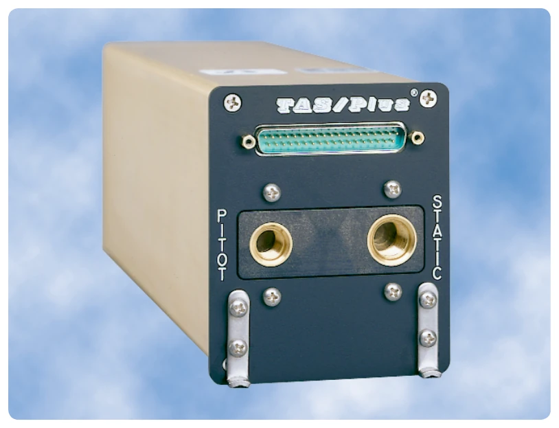
EFDs utilize the same type of instrument inputs as traditional analogue gauges; however, the processing system is different. The pitot static inputs are received by an ADC. The ADC computes the difference between the total pressure and the static pressure and generates the information necessary to display the airspeed on the PFD. Outside air temperatures are also monitored and introduced into various compo1nent2s within the system, as well as being displayed on the PFD screen. [Figure 8-15]
The ADC is a separate solid state device that, in addition to providing data to the PFD, is capable of providing data to the autopilot control system. In the event of system malfunction, 1the 1 ADC can quickly be removed and replaced in order to decrease downtime and decrease maintenance turn-around times.
Altitude information is derived from the static pressure port just as an analogue system does; however, the static press1ure 0
does not enter a diaphragm. The ADC computes the received barometric pressure and sends a digital signal to the PFD to display the proper altitude readout. EFDs also show trend vectors, which show the pilot how the altitude and airspeed are progressing.
Trend Vectors
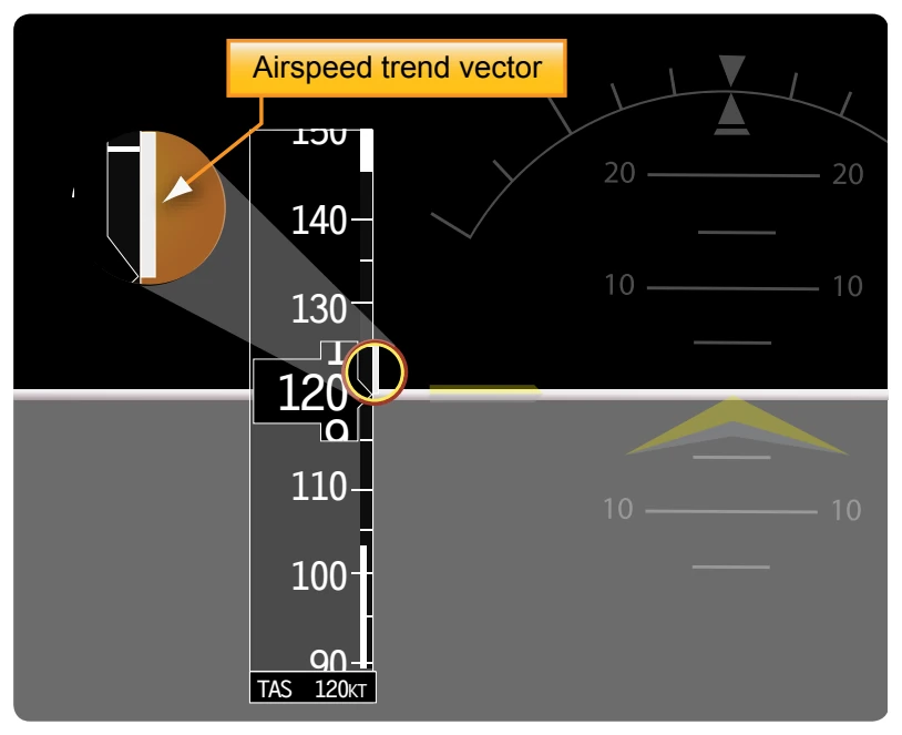
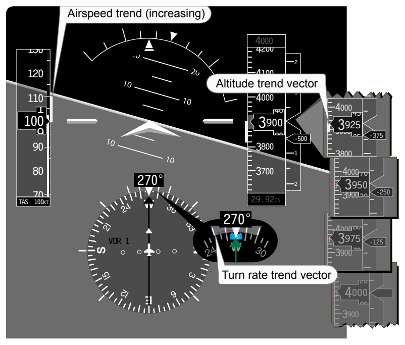
Trend vectors are magenta lines that move up and down both the ASI and the altimeter. [Figures 8-16 and 8-17] The ADC computes the rate of change and displays the 6-second projection of where the aircraft will be. Pilots can utilize the trend vectors to better control the aircraft’s attitude. By including the trend vectors in the instrument scan, pilots are able to precisely control airspeed and altitude. Additional information can be obtained by referencing the Instrument Flying Handbook or specific avionics manufacturer’s training material.
Gyroscopic Flight Instruments
Several flight instruments utilize the properties of a gyroscope for their operation. The most common instruments containing gyroscopes are the turn coordinator, heading indicator, and the attitude indicator. To understand how these instruments operate requires knowledge of the instrument power systems, gyroscopic principles, and the operating principles of each instrument.
Gyroscopic Principles
Any spinning object exhibits gyroscopic properties. A wheel or rotor designed and mounted to utilize these properties is called a gyroscope. Two important design characteristics of an instrument gyro are great weight for its size, or high density, and rotation at high speed with low friction bearings.