
Chapter 5
Aerodynamics of Flight
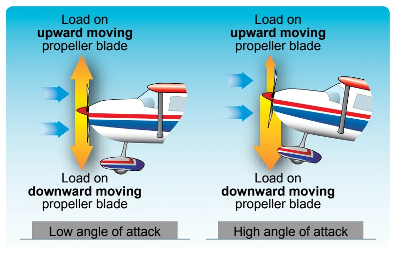
When an aircraft is flying with a high AOA, the “bite” of the downward moving blade is greater than the “bite” of the upward moving blade. This moves the center of thrust to the right of the prop disc area, causing a yawing moment toward the left around the vertical axis. Proving this explanation is complex because it would be necessary to work wind vector problems on each blade while considering both the AOA of the aircraft and the AOA of each blade.
This asymmetric loading is caused by the resultant velocity, which is generated by the combination of the velocity of the propeller blade in its plane of rotation and the velocity of the air passing horizontally through the propeller disc. With the aircraft being flown at positive AOAs, the right (viewed from the rear) or downswinging blade, is passing through an area of resultant velocity, which is greater than that affecting the left or upswinging blade. Since the propeller blade is an airfoil, increased velocity means increased lift. The downswinging blade has more lift and tends to pull (yaw) the aircraft’s nose to the left.
When the aircraft is flying at a high AOA, the downward moving blade has a higher resultant velocity, creating more lift than the upward moving blade. [Figure 5-51] This might be easier to visualize if the propeller shaft was mounted perpendicular to the ground (like a helicopter). If there were no air movement at all, except that generated by the propeller itself, identical sections of each blade would have the same airspeed. With air moving horizontally across this vertically mounted propeller, the blade proceeding forward into the flow of air has a higher airspeed than the blade retreating with the airflow. Thus, the blade proceeding into the horizontal airflow is creating more lift, or thrust, moving the center of thrust toward that blade. Visualize rotating the vertically mounted propeller shaft to shallower angles relative to the moving air (as on an aircraft). This unbalanced thrust then becomes proportionately smaller and continues getting smaller until it reaches the value of zero when the propeller shaft is exactly horizontal in relation to the moving air.
The effects of each of these four elements of torque vary in value with changes in flight situations. In one phase of flight, one of these elements may be more prominent than another. In another phase of flight, another element may be more prominent. The relationship of these values to each other varies with different aircraft depending on the airframe, engine, and propeller combinations, as well as other design features. To maintain positive control of the aircraft in all flight conditions, the pilot must apply the flight controls as necessary to compensate for these varying values.
Load Factors
In aerodynamics, the maximum load factor (at given bank angle) is a proportion between lift and weight and has a trigonometric relationship. The load factor is measured in Gs (acceleration of gravity), a unit of force equal to the force exerted by gravity on a body at rest and indicates the force to which a body is subjected when it is accelerated. Any force applied to an aircraft to deflect its flight from a straight line produces a stress on its structure. The amount of this force is the load factor. While a course in aerodynamics is not a prerequisite for obtaining a pilot’s license, the competent pilot should have a solid understanding of the forces that act on the aircraft, the advantageous use of these forces, and the operating limitations of the aircraft being flown.
In aerodynamics, the maximum load factor (at given bank angle) is a proportion between lift and weight and has a trigonometric relationship. The load factor is measured in Gs (acceleration of gravity), a unit of force equal to the force exerted by gravity on a body at rest and indicates the force to which a body is subjected when it is accelerated. Any force applied to an aircraft to deflect its flight from a straight line produces a stress on its structure. The amount of this force is the load factor. While a course in aerodynamics is not a prerequisite for obtaining a pilot’s license, the competent pilot should have a solid understanding of the forces that act on the aircraft, the advantageous use of these forces, and the operating limitations of the aircraft being flown.
For example, a load factor of 3 means the total load on an aircraft’s structure is three times its weight. Since load factors are expressed in terms of Gs, a load factor of 3 may be spoken of as 3 Gs, or a load factor of 4 as 4 Gs.
If an aircraft is pulled up from a dive, subjecting the pilot to 3 Gs, he or she would be pressed down into the seat with a force equal to three times his or her weight. Since modern aircraft operate at significantly higher speeds than older aircraft, increasing the potential for large load factors, this effect has become a primary consideration in the design of the structure of all aircraft.
With the structural design of aircraft planned to withstand only a certain amount of overload, a knowledge of load factors has become essential for all pilots. Load factors are important for two reasons:
- It is possible for a pilot to impose a dangerous overload on the aircraft structures.
- An increased load factor increases the stalling speed and makes stalls possible at seemingly safe flight speeds.
Load Factors in Aircraft Design
The answer to the question “How strong should an aircraft be?” is determined largely by the use to which the aircraft is subjected. This is a difficult problem because the maximum possible loads are much too high for use in efficient design. It is true that any pilot can make a very hard landing or an extremely sharp pull up from a dive, which would result in abnormal loads. However, such extremely abnormal loads must be dismissed somewhat if aircraft are built that take off quickly, land slowly, and carry worthwhile payloads.
The problem of load factors in aircraft design becomes how to determine the highest load factors that can be expected in normal operation under various operational situations. These load factors are called “limit load factors.” For reasons of safety, it is required that the aircraft be designed to withstand these load factors without any structural damage. Although the Code of Federal Regulations (CFR) requires the aircraft structure be capable of supporting one and one-half times these limit load factors without failure, it is accepted that parts of the aircraft may bend or twist under these loads and that some structural damage may occur.
This 1.5 load limit factor is called the “factor of safety” and provides, to some extent, for loads higher than those expected under normal and reasonable operation. This strength reserve is not something that pilots should willfully abuse; rather, it is there for protection when encountering unexpected conditions.
The above considerations apply to all loading conditions, whether they be due to gusts, maneuvers, or landings. The gust load factor requirements now in effect are substantially the same as those that have been in existence for years. Hundreds of thousands of operational hours have proven them adequate for safety. Since the pilot has little control over gust load factors (except to reduce the aircraft’s speed when rough air is encountered), the gust loading requirements are substantially the same for most general aviation type aircraft regardless of their operational use. Generally, the gust load factors control the design of aircraft which are intended for strictly nonacrobatic usage.
An entirely different situation exists in aircraft design with maneuvering load factors. It is necessary to discuss this matter separately with respect to: (1) aircraft designed in accordance with the category system (i.e., normal, utility, acrobatic); and (2) older designs built according to requirements that did not provide for operational categories.
Aircraft designed under the category system are readily identified by a placard in the flight deck, which states the operational category (or categories) in which the aircraft is certificated. The maximum safe load factors (limit load factors) specified for aircraft in the various categories are:
including spins)