
Chapter 5
Aerodynamics of Flight
Pilots can encounter icing in any season, anywhere in the country, at altitudes of up to 18,000 feet and sometimes higher. Small aircraft, including commuter planes, are most vulnerable because they fly at lower altitudes where ice is more prevalent. They also lack mechanisms common on jet aircraft that prevent ice buildup by heating the front edges of wings.
Icing can occur in clouds any time the temperature drops below freezing and super-cooled droplets build up on an aircraft and freeze. (Super-cooled droplets are still liquid even though the temperature is below 32 °Fahrenheit (F), or 0 °Celsius (C).
Angle of Attack Indicators
The FAA along with the General Aviation Joint Steering Committee (GAJSC) is promoting AOA indicators as one of the many safety initiatives aimed at reducing the general aviation accident rate. AOA indicators will specifically target Loss of Control (LOC) accidents. Loss of control is the number one root cause of fatalities in both general aviation and commercial aviation. More than 25 percent of general aviation fatal accidents occur during the maneuvering phase of flight. Of those accidents, half involve stall/spin scenarios. Technology such as AOA indicators can have a tremendous impact on reversing this trend and are increasingly affordable for general aviation airplanes. [Figure 5-41]
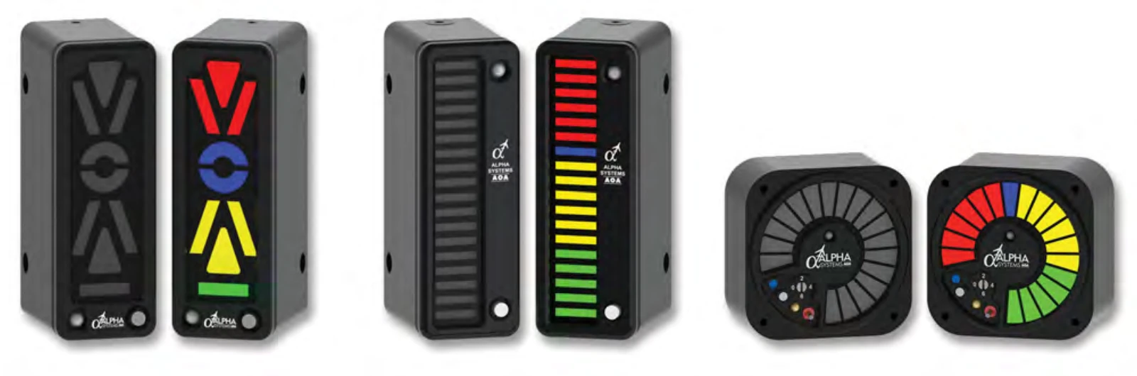
The purpose of an AOA indicator is to give the pilot better situation awareness pertaining to the aerodynamic health of the airfoil. This can also be referred to as stall margin awareness. More simply explained, it is the margin that exists between the current AOA that the airfoil is operating at, and the AOA at which the airfoil will stall (critical AOA).
Angle of attack is taught to student pilots as theory in ground training. When beginning flight training, students typically rely solely on airspeed and the published 1G stall speed to avoid stalls. This creates problems since this speed is only valid when the following conditions are met:
- Unaccelerated flight (a 1G load factor)
- Coordinated flight (inclinometer centered)
- At one weight (typically maximum gross weight)
Speed by itself is not a reliable parameter to avoid a stall. An airplane can stall at any speed. Angle of attack is a better parameter to use to avoid a stall. For a given configuration, the airplane always stalls at the same AOA, referred to as the critical AOA. This critical AOA does not change with:
- Weight
- Bank angle
- Temperature
- Density altitude
- Center of gravity
An AOA indicator can have several benefits when installed in general aviation aircraft, not the least of which is increased situational awareness. Without an AOA indicator, the AOA is “invisible” to pilots. These devices measure several parameters simultaneously and determine the current AOA providing a visual image to the pilot of the current AOA along with representations of the proximity to the critical AOA. [Figure 5-42] These devices can give a visual representation of the energy management state of the airplane. The energy state of an airplane is the balance between airspeed, altitude, drag, and thrust and represents how efficiently the airfoil is operating. The more efficiently the airfoil operates; the larger stall margin that is present. With this increased situational awareness pertaining to the energy condition of the airplane, pilots will have information that they need to aid in preventing a LOC scenario resulting from a stall/spin. Additionally, the less energy that is utilized to maintain flight means greater overall efficiency of the airplane, which is typically realized in fuel savings. This equates to a lower operating cost to the pilot.
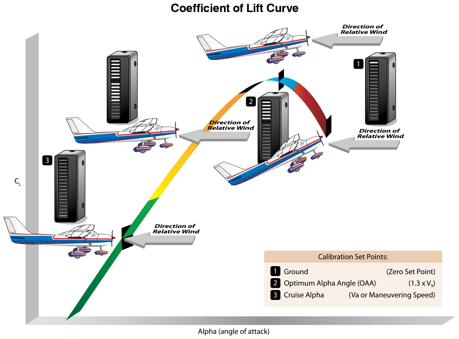
Just as training is required for any system on an aircraft, AOA indicators have training considerations also. A more comprehensive understanding of AOA in general should be the goal of this training along with the specific operating characteristics and limitations of the installed AOA indicator. Ground and flight instructors should make every attempt to receive training from an instructor knowledgeable about AOA indicators prior to giving instruction pertaining to or in airplanes equipped with AOA indicators. Pilot schools should incorporate training on AOA indicators in their syllabi, whether their training aircraft are equipped with them or not.
Installation of AOA indicators not required by type certification in general aviation airplanes has recently been streamlined by the FAA. The FAA established policy in February 2014 pertaining to non-required AOA systems and how they may be installed as a minor alteration, depending upon their installation requirements and operational utilization, and the procedures to take for certification of these installations. For updated information, reference the FAA website at www.faa.gov.
While AOA indicators provide a simple visual representation of the current AOA and its proximity to the critical AOA, they are not without their limitations. These limitations should be understood by operators of general aviation airplanes equipped with these devices. Like advanced automation, such as autopilots and moving maps, the misunderstanding or misuse of the equipment can have disastrous results. Some items which may limit the effectiveness of an AOA indicator are listed below:
- Calibration techniques
- Probes or vanes not being heated
- The type of indicator itself
- Flap setting
- Wing contamination
Pilots of general aviation airplanes equipped with AOA indicators should contact the manufacturer for specific limitations applicable to that installation.
Basic Propeller Principles
The aircraft propeller consists of two or more blades and a central hub to which the blades are attached. Each blade of an aircraft propeller is essentially a rotating wing. As a result of their construction, the propeller blades are like airfoils and produce forces that create the thrust to pull, or push, the aircraft through the air. The engine furnishes the power needed to rotate the propeller blades through the air at high speeds, and the propeller transforms the rotary power of the engine into forward thrust.
A cross-section of a typical propeller blade is shown in Figure 5-43. This section or blade element is an airfoil comparable to a cross-section of an aircraft wing. One surface of the blade is cambered or curved, similar to the upper surface of an aircraft wing, while the other surface is flat like the bottom surface of a wing. The chord line is an imaginary line drawn through the blade from its leading edge to its trailing edge. As in a wing, the leading edge is the thick edge of the blade that meets the air as the propeller rotates. Blade angle, usually measured in degrees, is the angle between the chord of the blade and the plane of rotation and is measured at a specific point along the length of the blade. [Figure 5-44] Because most propellers have a flat blade “face,” the chord line is often drawn along the face of the propeller blade. Pitch is not blade angle, but because pitch is largely determined by blade angle, the two terms are often used interchangeably. An increase or decrease in one is usually associated with an increase or decrease in the other. The pitch of a propeller may be designated in inches. A propeller designated as a “74–48” would be 74 inches in length and have an effective pitch of 48 inches. The pitch is the distance in inches, which the propeller would screw through the air in one revolution if there were no slippage.