Chapter 4
Principles of Flight
Newton’s Third Law: “For every action, there is an equal and opposite reaction.”
In an airplane, the propeller moves and pushes back the air; consequently, the air pushes the propeller (and thus the airplane) in the opposite direction—forward. In a jet airplane, the engine pushes a blast of hot gases backward; the force of equal and opposite reaction pushes against the engine and forces the airplane forward.
Bernoulli’s Principle of Differential Pressure
A half-century after Newton formulated his laws, Daniel Bernoulli, a Swiss mathematician, explained how the pressure of a moving fluid (liquid or gas) varies with its speed of motion. Bernoulli’s Principle states that as the velocity of a moving fluid (liquid or gas) increases, the pressure within the fluid decreases. This principle explains what happens to air passing over the curved top of the airplane wing.
A practical application of Bernoulli’s Principle is the venturi tube. The venturi tube has an air inlet that narrows to a throat (constricted point) and an outlet section that increases in diameter toward the rear. The diameter of the outlet is the same as that of the inlet. The mass of air entering the tube must exactly equal the mass exiting the tube. At the constriction, the speed must increase to allow the same amount of air to pass in the same amount of time as in all other parts of the tube. When the air speeds up, the pressure also decreases. Past the constriction, the airflow slows and the pressure increases. [Figure 4-4]
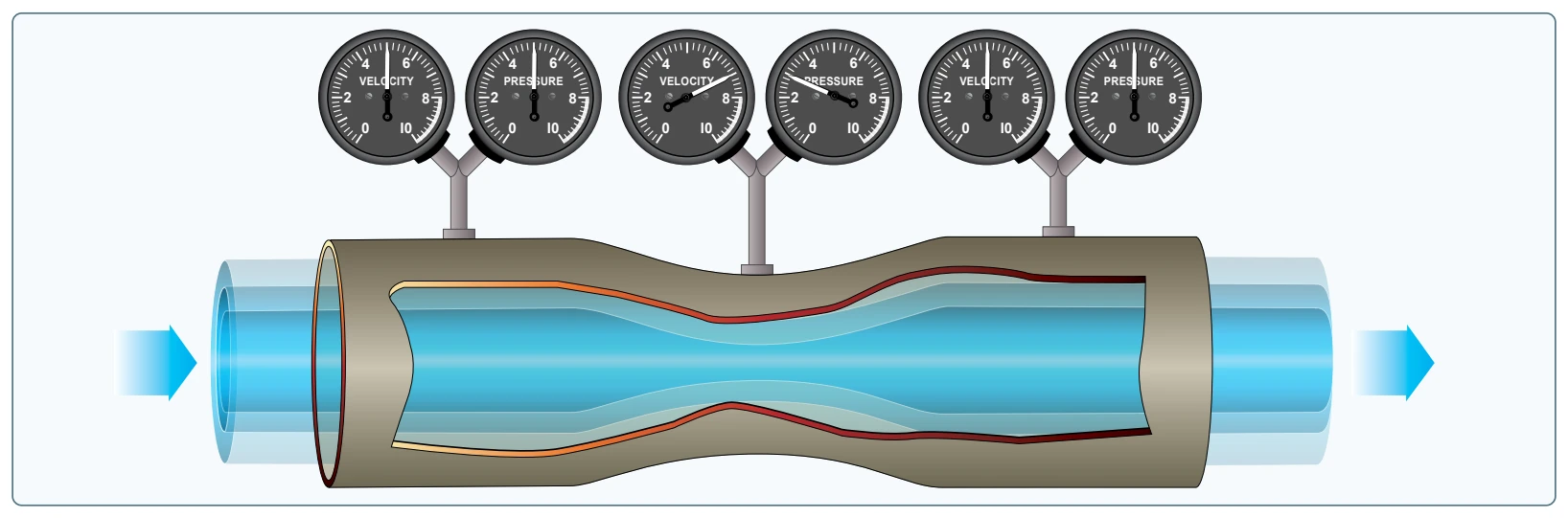
Since air is recognized as a body, and it is understood that air will follow the above laws, one can begin to see how and why an airplane wing develops lift. As the wing moves through the air, the flow of air across the curved top surface increases in velocity creating a low-pressure area.
Although Newton, Bernoulli, and hundreds of other early scientists who studied the physical laws of the universe did not have the sophisticated laboratories available today, they provided great insight to the contemporary viewpoint of how lift is created.
Airfoil Design
An airfoil is a structure designed to obtain reaction upon its surface from the air through which it moves or that moves past such a structure. Air acts in various ways when submitted to different pressures and velocities; but this discussion is confined to the parts of an aircraft that a pilot is most concerned with in flight—namely, the airfoils designed to produce lift. By looking at a typical airfoil profile, such as the cross section of a wing, one can see several obvious characteristics of design. [Figure 4-5] Notice that there is a difference in the curvatures (called cambers) of the upper and lower surfaces of the airfoil. The camber of the upper surface is more pronounced than that of the lower surface, which is usually somewhat flat.
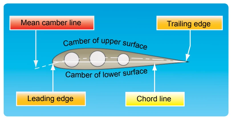
NOTE: The two extremities of the airfoil profile also differ in appearance. The rounded end, which faces forward in flight, is called the leading edge; the other end, the trailing edge, is quite narrow and tapered.
A reference line often used in discussing the airfoil is the chord line, a straight line drawn through the profile connecting the extremities of the leading and trailing edges. The distance from this chord line to the upper and lower surfaces of the wing denotes the magnitude of the upper and lower camber at any point. Another reference line, drawn from the leading edge to the trailing edge, is the mean camber line. This mean line is equidistant at all points from the upper and lower surfaces.
An airfoil is constructed in such a way that its shape takes advantage of the air’s response to certain physical laws. This develops two actions from the air mass: a positive pressure lifting action from the air mass below the wing, and a negative pressure lifting action from lowered pressure above the wing.
As the air stream strikes the relatively flat lower surface of a wing or rotor blade when inclined at a small angle to its direction of motion, the air is forced to rebound downward, causing an upward reaction in positive lift. At the same time, the air stream striking the upper curved section of the leading edge is deflected upward. An airfoil is shaped to cause an action on the air, and forces air downward, which provides an equal reaction from the air, forcing the airfoil upward. If a wing is constructed in such form that it causes a lift force greater than the weight of the aircraft, the aircraft will fly.
If all the lift required were obtained merely from the deflection of air by the lower surface of the wing, an aircraft would only need a flat wing like a kite. However, the balance of the lift needed to support the aircraft comes from the flow of air above the wing. Herein lies the key to flight.
It is neither accurate nor useful to assign specific values to the percentage of lift generated by the upper surface of an airfoil versus that generated by the lower surface. These are not constant values. They vary, not only with flight conditions, but also with different wing designs.
Different airfoils have different flight characteristics. Many thousands of airfoils have been tested in wind tunnels and in actual flight, but no one airfoil has been found that satisfies every flight requirement. The weight, speed, and purpose of each aircraft dictate the shape of its airfoil. The most efficient airfoil for producing the greatest lift is one that has a concave or “scooped out” lower surface. As a fixed design, this type of airfoil sacrifices too much speed while producing lift and is not suitable for high-speed flight. Advancements in engineering have made it possible for today’s high-speed jets to take advantage of the concave airfoil’s high lift characteristics. Leading edge (Kreuger) flaps and trailing edge (Fowler) flaps, when extended from the basic wing structure, literally change the airfoil shape into the classic concave form, thereby generating much greater lift during slow flight conditions.
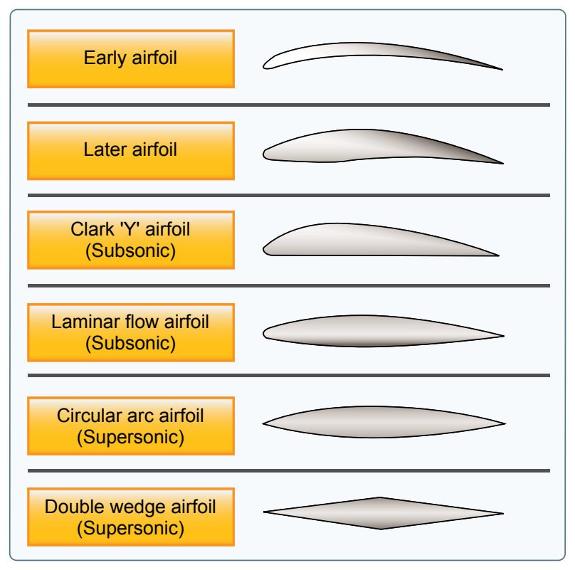
On the other hand, an airfoil that is perfectly streamlined and offers little wind resistance sometimes does not have enough lifting power to take the airplane off the ground. Thus, modern airplanes have airfoils that strike a medium between extremes in design. The shape varies according to the needs of the airplane for which it is designed. Figure 4-6 shows some of the more common airfoil designs.