
Chapter 3
Aircraft Construction
There are two significant factors involved in the design of a propeller that impact its effectiveness. The angle of a propeller blade, as measured against the hub of the propeller, keeps the angle of attack (AOA) (See definition in Glossary) relatively constant along the span of the propeller blade, reducing or eliminating the possibility of a stall. The amount of lift being produced by the propeller is directly related to the AOA, which is the angle at which the relative wind meets the blade. The AOA continuously changes during the flight depending upon the direction of the aircraft.
The pitch is defined as the distance a propeller would travel in one revolution if it were turning in a solid. These two factors combine to allow a measurement of the propeller’s efficiency. Propellers are usually matched to a specific aircraft/ powerplant combination to achieve the best efficiency at a particular power setting, and they pull or push depending on how the engine is mounted.
Subcomponents
The subcomponents of an airplane include the airframe, electrical system, flight controls, and brakes.
The airframe is the basic structure of an aircraft and is designed to withstand all aerodynamic forces, as well as the stresses imposed by the weight of the fuel, crew, and payload.
The primary function of an aircraft electrical system is to generate, regulate, and distribute electrical power throughout the aircraft. There are several different power sources on aircraft to power the aircraft electrical systems. These power sources include: engine-driven alternating current (AC) generators, auxiliary power units (APUs), and external power. The aircraft’s electrical power system is used to operate the flight instruments, essential systems, such as anti-icing, and passenger services, such as cabin lighting.
The flight controls are the devices and systems that govern the attitude of an aircraft and, as a result, the flight path followed by the aircraft. In the case of many conventional airplanes, the primary flight controls utilize hinged, trailing- edge surfaces called elevators for pitch, ailerons for roll, and the rudder for yaw. These surfaces are operated by the pilot in the flight deck or by an automatic pilot.
In the case of most modern airplanes, airplane brakes consist of multiple pads (called caliper pads) that are hydraulically squeezed toward each other with a rotating disk (called a rotor) between them. The pads place pressure on the rotor which is turning with the wheels. As a result of the increased friction on the rotor, the wheels inherently slow down and stop turning. The disks and brake pads are made either from steel, like those in a car, or from a carbon material that weighs less and can absorb more energy. Because airplane brakes are used principally during landings and must absorb enormous amounts of energy, their life is measured in landings rather than miles.
Types of Aircraft Construction
The construction of aircraft fuselages evolved from the early wood truss structural arrangements to monocoque shell structures to the current semimonocoque shell structures.
Truss Structure
The main drawback of truss structure is its lack of a streamlined shape. In this construction method, lengths of tubing, called longerons, are welded in place to form a well- braced framework. Vertical and horizontal struts are welded to the longerons and give the structure a square or rectangular shape when viewed from the end. Additional struts are needed to resist stress that can come from any direction. Stringers and bulkheads, or formers, are added to shape the fuselage and support the covering.
As technology progressed, aircraft designers began to enclose the truss members to streamline the airplane and improve performance. This was originally accomplished with cloth fabric, which eventually gave way to lightweight metals such as aluminum. In some cases, the outside skin can support all or a major portion of the flight loads. Most modern aircraft use a form of this stressed skin structure known as monocoque or semimonocoque construction. [Figure 3-14]
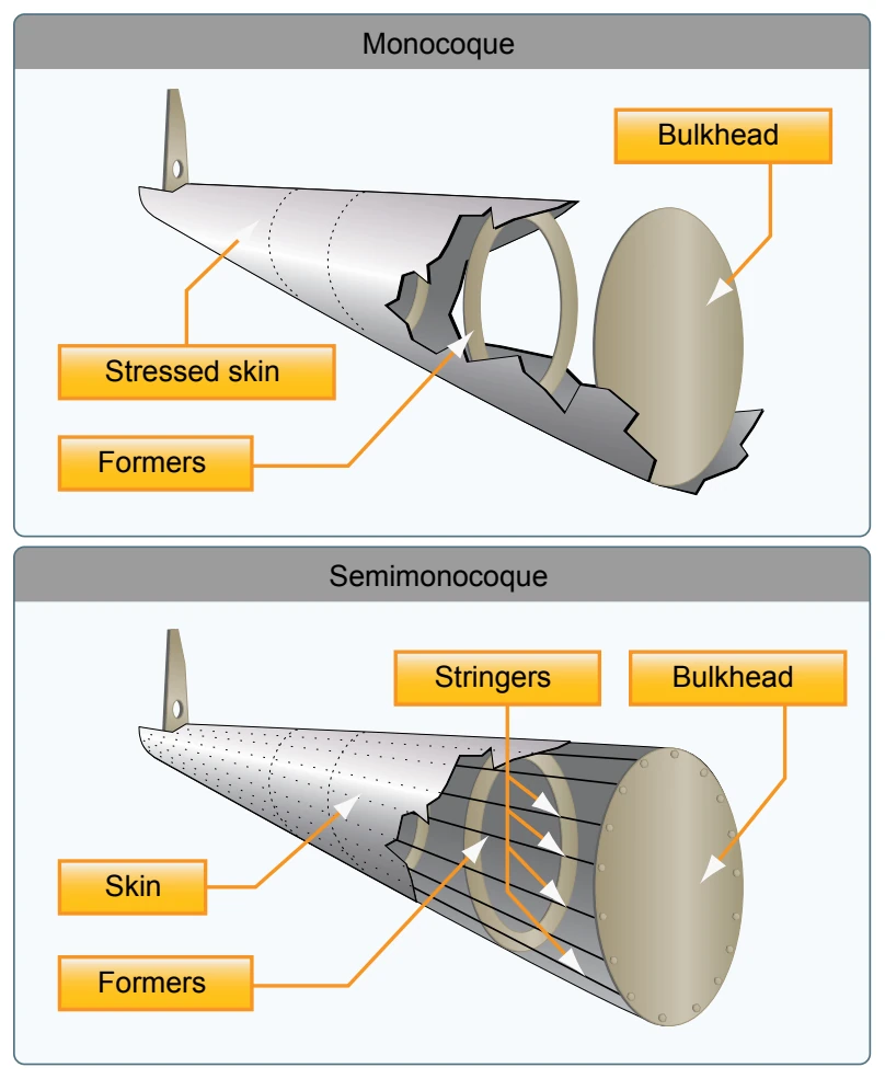
Monocoque
Monocoque construction uses stressed skin to support almost all loads much like an aluminum beverage can. Although very strong, monocoque construction is not highly tolerant to deformation of the surface. For example, an aluminum beverage can supports considerable forces at the ends of the can, but if the side of the can is deformed slightly while supporting a load, it collapses easily.
Because most twisting and bending stresses are carried by the external skin rather than by an open framework, the need for internal bracing was eliminated or reduced, saving weight and maximizing space. One of the notable and innovative methods for using monocoque construction was employed by Jack Northrop. In 1918, he devised a new way to construct a monocoque fuselage used for the Lockheed S-1 Racer. The technique utilized two molded plywood half-shells that were glued together around wooden hoops or stringers. To construct the half shells, rather than gluing many strips of plywood over a form, three large sets of spruce strips were soaked with glue and laid in a semi-circular concrete mold that looked like a bathtub. Then, under a tightly clamped lid, a rubber balloon was inflated in the cavity to press the plywood against the mold. Twenty-four hours later, the smooth half-shell was ready to be joined to another to create the fuselage. The two halves were each less than a quarter inch thick. Although employed in the early aviation period, monocoque construction would not reemerge for several decades due to the complexities involved. Every day examples of monocoque construction can be found in automobile manufacturing where the unibody is considered standard in manufacturing.
Semimonocoque
Semimonocoque construction, partial or one-half, uses a substructure to which the airplane’s skin is attached. The substructure, which consists of bulkheads and/or formers of various sizes and stringers, reinforces the stressed skin by taking some of the bending stress from the fuselage. The main section of the fuselage also includes wing attachment points and a firewall. On single-engine airplanes, the engine is usually attached to the front of the fuselage. There is a fireproof partition between the rear of the engine and the flight deck or cabin to protect the pilot and passengers from accidental engine fires. This partition is called a firewall and is usually made of heat-resistant material such as stainless steel. However, a new emerging process of construction is the integration of composites or aircraft made entirely of composites.