
Chapter 16
Navigation
Now, the GS can be determined. This is done using a manual or electronic calculator. The GS is determined to be 106 knots. Based on this information, the total trip time, as well as time between checkpoints, and the fuel burned can be determined. These numbers can be calculated by using a manual or electronic calculator.
For this trip, the GS is 106 knots and the total time is 35 minutes (30 minutes plus 5 minutes for climb) with a fuel burn of 4.7 gallons. Refer to the flight log in Figure 16-26 for the time between checkpoints.
As the trip progresses, the pilot can note headings and time and make adjustments in heading, GS, and time.
Filing a VFR Flight Plan
Filing a flight plan is not required by regulations; however, it is a good operating practice since the information contained in the flight plan can be used in search and rescue in the event of an emergency.
Flight plans can be filed in the air by radio, but it is best to file a flight plan by phone just before departing. After takeoff, contact the FSS by radio and give them the takeoff time so the flight plan can be activated.
When a VFR flight plan is filed, it is held by the FSS until 1 hour after the proposed departure time and then canceled unless: the actual departure time is received; a revised proposed departure time is received; or at the time of filing, the FSS is informed that the proposed departure time is met, but actual time cannot be given because of inadequate communication. The FSS specialist who accepts the flight plan does not inform the pilot of this procedure, however.
FSS. When filing a flight plan by telephone or radio, give the information in the order of the numbered spaces. This enables the FSS specialist to copy the information more efficiently. Most of the fields are either self-explanatory or non-applicable to the VFR flight plan (such as item 13). However, some fields may need explanation.
- Item 3 is the aircraft type and special equipment. An example would be C-150/X, which means the aircraft has no transponder. A listing of special equipment codes is found in the Aeronautical Information Manual (AIM).
- Item 6 is the proposed departure time in UTC (indicated by the “Z”).
- Item 7 is the cruising altitude. Normally, “VFR” can be entered in this block since the pilot chooses a cruising altitude to conform to FAA regulations.
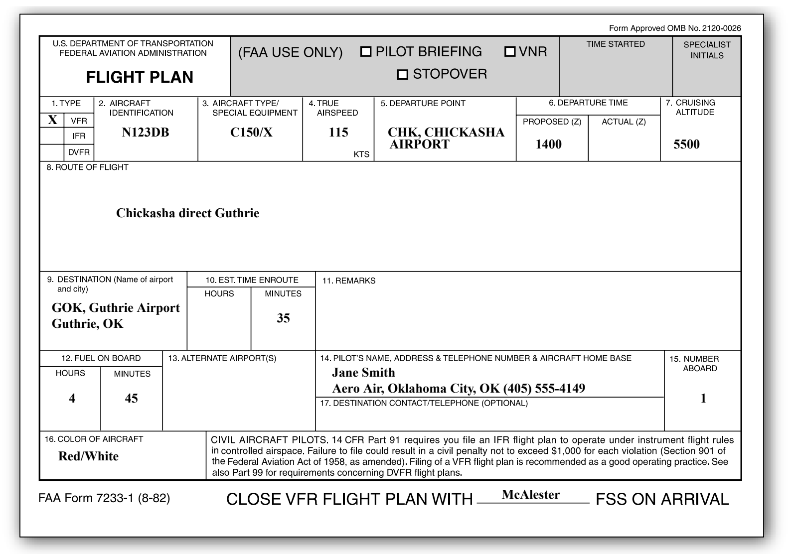
- Item 8 is the route of flight. If the flight is to be direct, enter the word “direct;” if not, enter the actual route to be followed, such as via certain towns or navigation aids.
- Item 10 is the estimated time en route. In the sample flight plan, 5 minutes was added to the total time to allow for the climb.
- Item 12 is the fuel on board in hours and minutes. This is determined by dividing the total usable fuel aboard in gallons by the estimated rate of fuel consumption in gallons.
Remember, there is every advantage in filing a flight plan; but do not forget to close the flight plan upon arrival. This should be done via telephone to avoid radio congestion.
Ground-Based Navigation
Advances in navigational radio receivers installed in aircraft, the development of aeronautical charts that show the exact location of ground transmitting stations and their frequencies, along with refined flight deck instrumentation make it possible for pilots to navigate with precision to almost any point desired. Although precision in navigation is obtainable through the proper use of this equipment, beginning pilots should use this equipment to supplement navigation by visual reference to the ground (pilotage). This method provides the pilot with an effective safeguard against disorientation in the event of radio malfunction.
There are three radio navigation systems available for use for VFR navigation. These are:
- VHF Omnidirectional Range (VOR)
- Nondirectional Radio Beacon (NDB)
- Global Positioning System (GPS)
Very High Frequency (VHF) Omnidirectional Range (VOR)
The VOR system is present in three slightly different navigation aids (NAVAIDs): VOR, VOR/distance measuring equipment (DME)(discussed in a later section), and VORTAC. By itself it is known as a VOR, and it provides magnetic bearing information to and from the station. When DME is also installed with a VOR, the NAVAID is referred to as a VOR/DME. When military tactical air navigation (TACAN) equipment is installed with a VOR, the NAVAID is known as a VORTAC. DME is always an integral part of a VORTAC. Regardless of the type of NAVAID utilized (VOR, VOR/DME, or VORTAC), the VOR indicator behaves the same. Unless otherwise noted in this section, VOR, VOR/DME, and VORTAC NAVAIDs are all referred to hereafter as VORs.
The prefix “omni-” means all, and an omnidirectional range is a VHF radio transmitting ground station that projects straight line courses (radials) from the station in all directions. From a top view, it can be visualized as being similar to the spokes from the hub of a wheel. The distance VOR radials are projected depends upon the power output of the transmitter.
The course or radials projected from the station are referenced to MN. Therefore, a radial is defined as a line of magnetic bearing extending outward from the VOR station. Radials are identified by numbers beginning with 001, which is 1° east of MN and progress in sequence through all the degrees of a circle until reaching 360. To aid in orientation, a compass rose reference to magnetic north is superimposed on aeronautical charts at the station location.