Chapter 14
Airport Operations
intersects ahead at 90° both left and right.
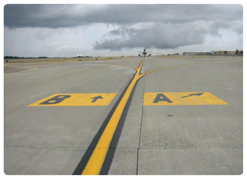
Taxiway direction signs can also be displayed as surface painted markings. Figure 14-19 shows Taxiway Bravo as proceeding straight ahead while Taxiway Alpha turns to the right at approximately 45°.
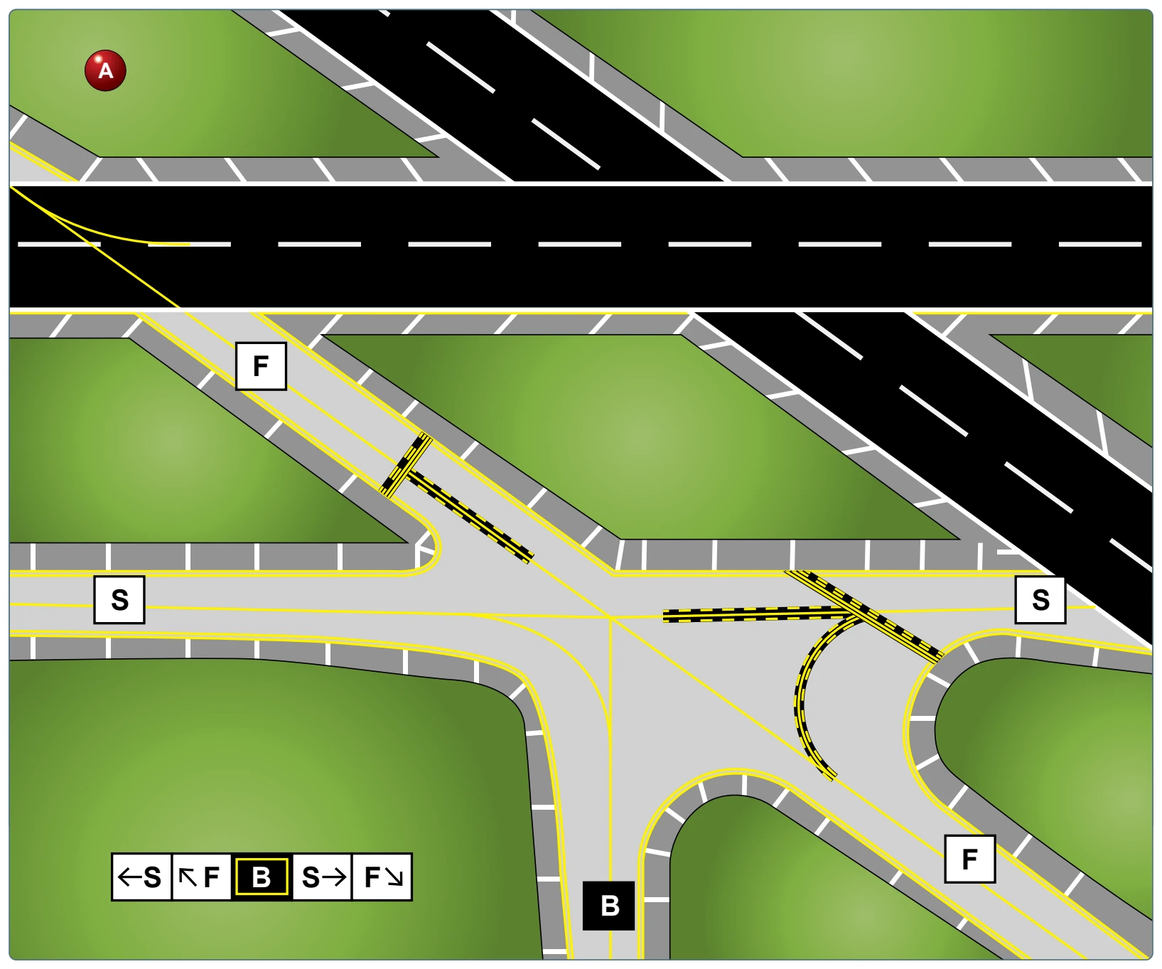
a complex taxiway intersection. Figure 14-20A and B shows Taxiway Bravo intersects with Taxiway Sierra at 90°, but at 45° with Taxiway Foxtrot. This type of array can be displayed with or without the taxiway location sign, which in this case would be Taxiway Bravo.
Enhanced Taxiway Centerline Markings
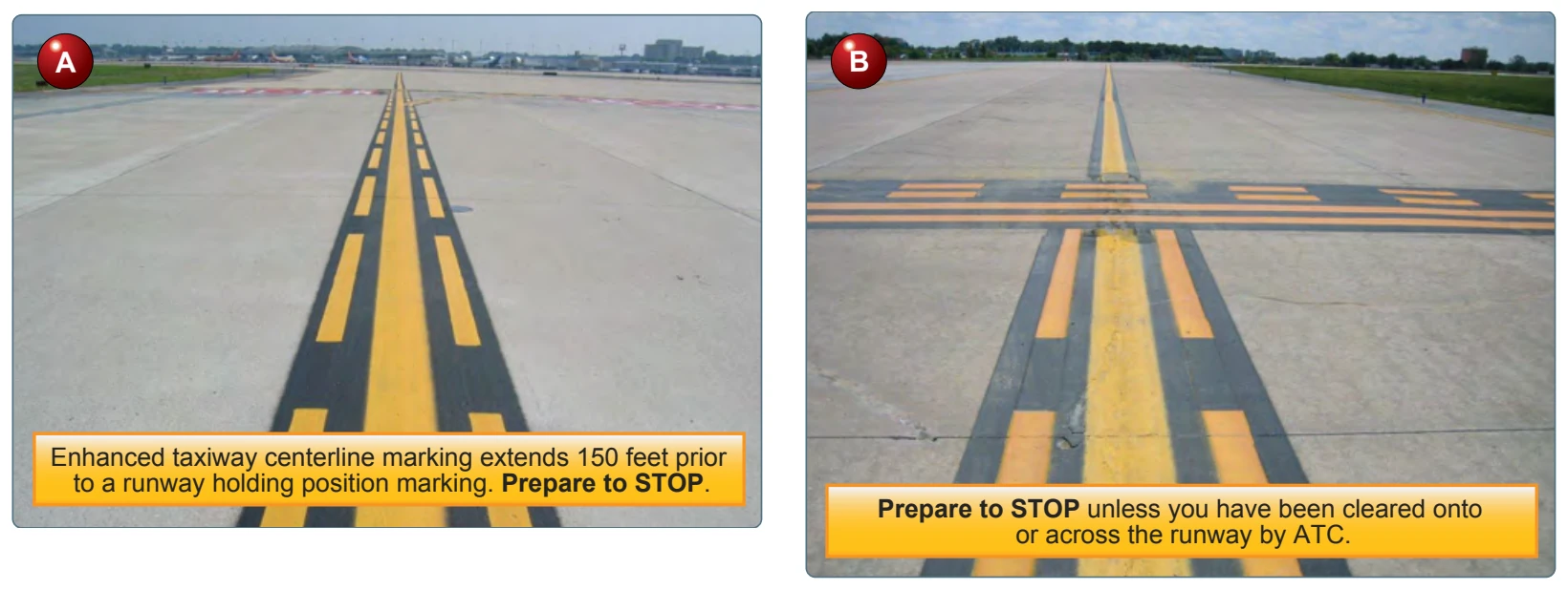
At most towered airports, the enhanced taxiway centerline marking is used to warn you of an upcoming runway. It consists of yellow dashed lines on either side of the normal solid taxiway centerline and the dashes extend up to 150 feet prior to a runway holding position marking. [Figure 14-21A and B] They are used to aid you in maintaining awareness during surface movement to reduce runway incursions.
Destination Signs
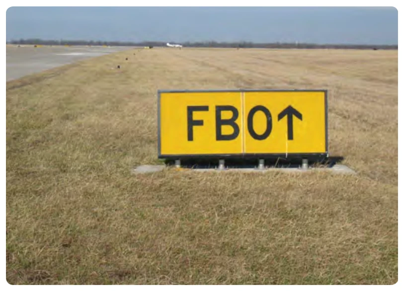
Destination signs have black characters on a yellow background indicating a destination at the airport. These
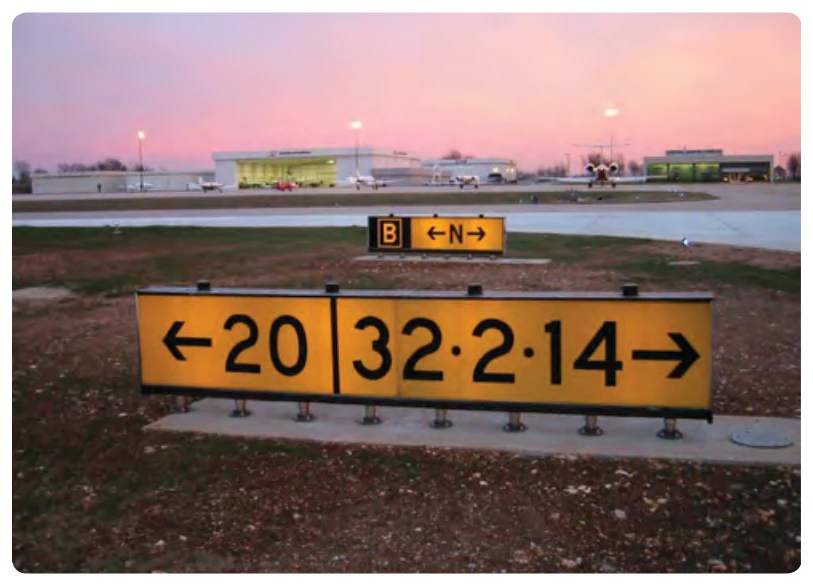
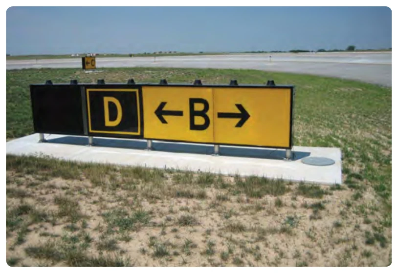
signs always have an arrow showing the direction of the taxi route to that destination. [Figure 14-22] When the arrow on the destination sign indicates a turn, the sign is located prior to the intersection. Destinations commonly shown on these types of signs include runways, aprons, terminals, military areas, civil aviation areas, cargo areas, international areas, and fixed-base operators. When the inscription for two or more destinations having a common taxi route are placed on a sign, the destinations are separated by a “dot” (•) and one arrow would be used as shown in Figure 14-22. When the inscription on a sign contains two or more destinations having different taxi routes, each destination is accompanied by an arrow and separated from the other destination(s) on the sign with a vertical black message divider as shown in
two signs. The sign in the foreground explains that Runway 20 threshold is to the left, and Runways 32, 2, and 14 are to the right. The sign in the background indicates that you are located on Taxiway Bravo and Taxiway November will take you to those runways.
Holding Position Signs and Markings for an Instrument Landing System (ILS) Critical Area
The instrument landing system (ILS) broadcasts signals to arriving instrument aircraft to guide them to the runway. Each of these ILSs have critical areas that must be kept clear of all obstacles in order to ensure quality of the broadcast signal. At many airports, taxiways extend into the ILS critical area. Most of the time, this is of no concern; however, during times of poor weather, an aircraft on approach may depend on a good signal quality. When necessary, ATC will protect the ILS critical area for arrival instrument traffic by instructing taxiing aircraft to “hold short” of Runway (XX) ILS critical area.
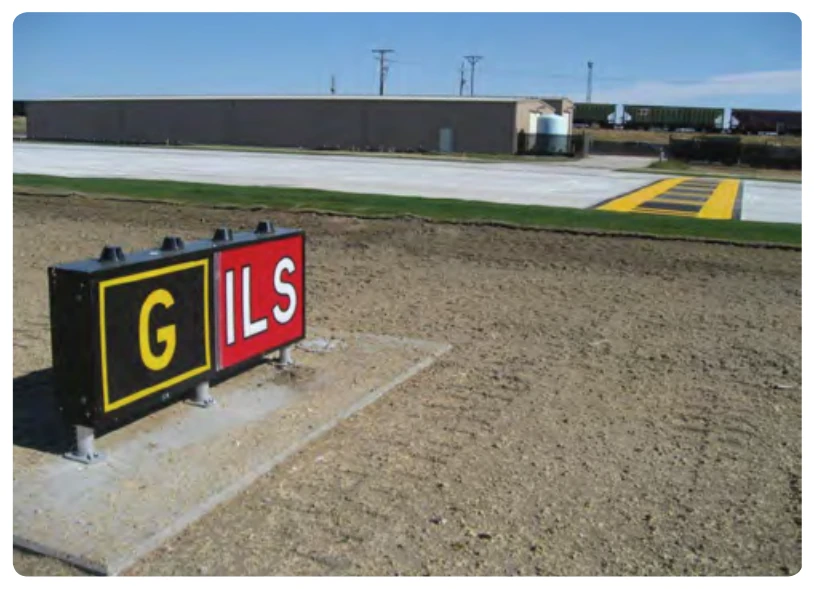
The ILS critical area hold sign has white characters, outlined in black, on a red background and is installed adjacent to the ILS holding position markings. [Figure 14-24] The holding position markings for the ILS critical area appear on the pavement as a horizontal yellow ladder extending across the width of the taxiway.
When instructed to “hold short of Runway (XX) ILS critical area,” you must ensure no portion of the aircraft extends beyond these markings. [Figure 14-25] If ATC does not instruct you to hold at this point, then you may bypass the ILS critical area hold position markings and continue with your taxi. Figure 14-24 shows that the ILS hold sign is located on Taxiway Golf and the ILS ladder hold position marking is adjacent to the hold sign.