Chapter 10
Weight and Balance
Weight and Balance Restrictions
An aircraft’s weight and balance restrictions should be closely followed. The loading conditions and empty weight of a particular aircraft may differ from that found in the AFM/POH because modifications or equipment changes may have been made. Sample loading problems in the AFM/POH are intended for guidance only; therefore, each aircraft must be treated separately. Although an aircraft is certified for a specified maximum gross takeoff weight, it may not safely take off at this weight under all conditions. Conditions that affect takeoff and climb performance, such as high elevations, high temperatures, and high humidity (high density altitudes), may require a reduction in weight before flight is attempted. Other factors to consider when computing
weight and balance distribution prior to takeoff are runway length, runway surface, runway slope, surface wind, and the presence of obstacles. These factors may require a reduction in or redistribution of weight prior to flight.
Some aircraft are designed so that it is difficult to load them in a manner that places the CG out of limits. These are usually small aircraft with the seats, fuel, and baggage areas located near the CG limit. Pilots must be aware that while within CG limits these aircraft can be overloaded in weight. Other aircraft can be loaded in such a manner that they will be out of CG limits even though the useful load has not been exceeded. Because of the effects of an out-of-balance or overweight condition, a pilot should always be sure that an aircraft is properly loaded.
Determining Loaded Weight and CG
There are various methods for determining the loaded weight and CG of an aircraft. There is the computational method as well as methods that utilize graphs and tables provided by the aircraft manufacturer.
Computational Method
The following is an example of the computational method involving the application of basic math functions. Aircraft Allowances: Maximum gross weight......................3,400 pounds CG range.............................................78-86 inches Given: Weight of front seat occupants.............340 pounds Weight of rear seat occupants..............350 pounds Fuel...........................................................75 gallons Weight of baggage in area 1....................80 pounds
- List the weight of the aircraft, occupants, fuel, and baggage. Remember that aviation gas (AVGAS) weighs 6 pounds per gallon and is used in this example.
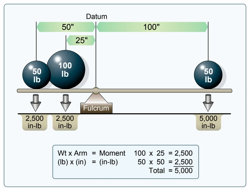
- Enter the moment for each item listed. Remember “weight x arm = moment.”
- Find the total weight and total moment.
- To determine the CG, divide the total moment by the total weight.
NOTE: The weight and balance records for a particular aircraft provide the empty weight and moment, as well as the information on the arm distance. [Figure 10-5]
The total loaded weight of 3,320 pounds does not exceed the maximum gross weight of 3,400 pounds, and the CG of

84.8 is within the 78-86 inch range; therefore, the aircraft is loaded within limits.
Graph Method
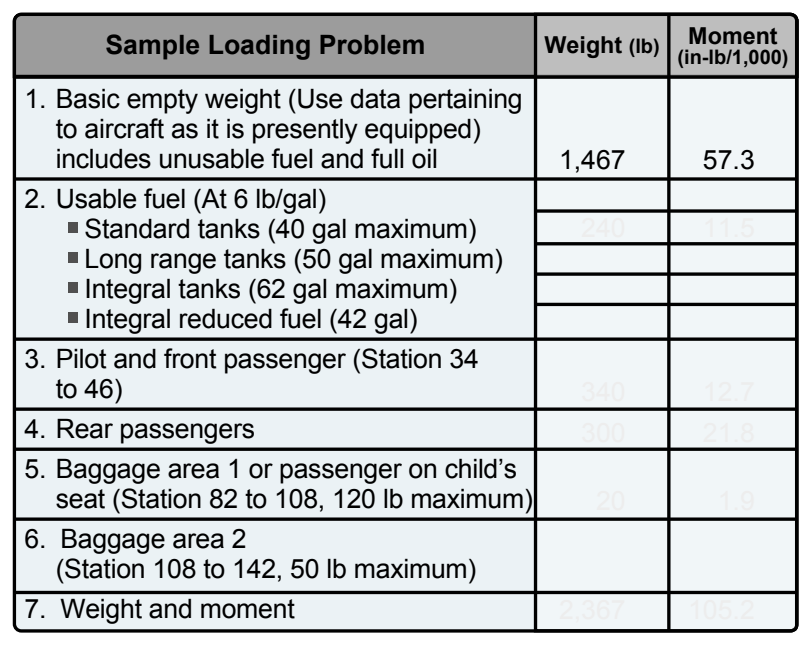
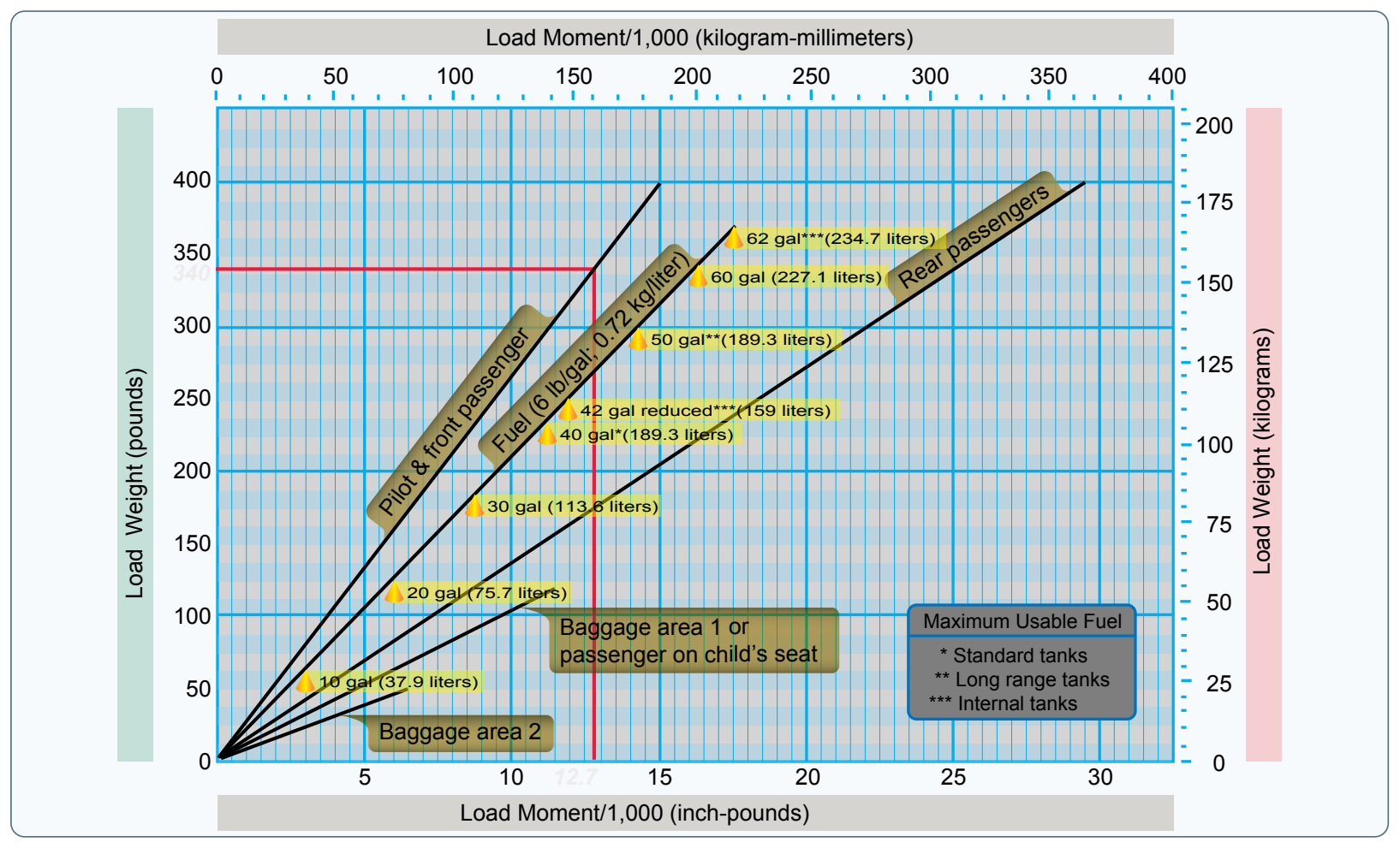
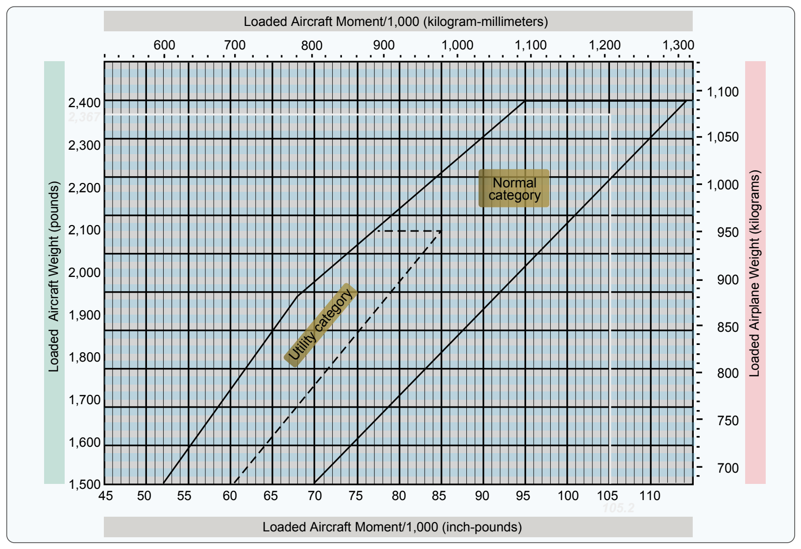
Another method for determining the loaded weight and CG is the use of graphs provided by the manufacturers. To simplify calculations, the moment may sometimes be divided by 100, 1,000, or 10,000. [Figures 10-6, 10-7, and 10-8] Front seat occupants....................................340 pounds Rear seat occupants......................................300 pounds Fuel.................................................................40 gallons Baggage area 1...............................................20 pounds
The same steps should be followed in the graph method as were used in the computational method except the graphs provided will calculate the moments and allow the pilot to determine if the aircraft is loaded within limits. To determine the moment using the loading graph, find the weight and draw a line straight across until it intercepts the item for which the moment is to be calculated. Then draw a line straight down to determine the moment. (The red line on the loading graph in Figure 10-7 represents the moment for the pilot and front passenger. All other moments were determined the same