
Chapter 4
Energy Management: Mastering Altitude and Airspeed Control
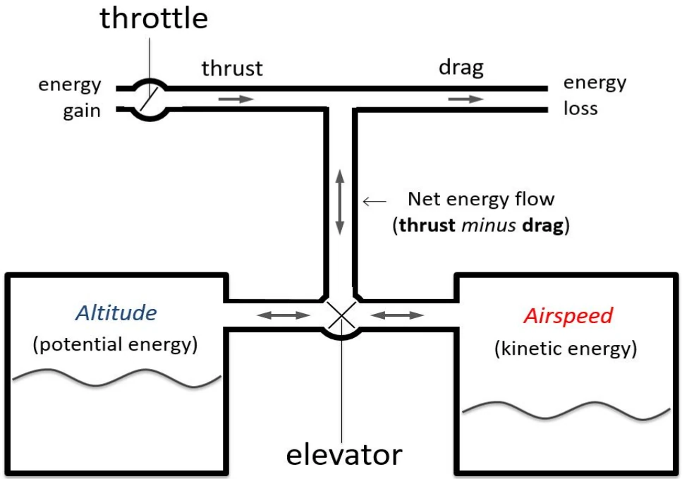
Additional Role for the Elevator
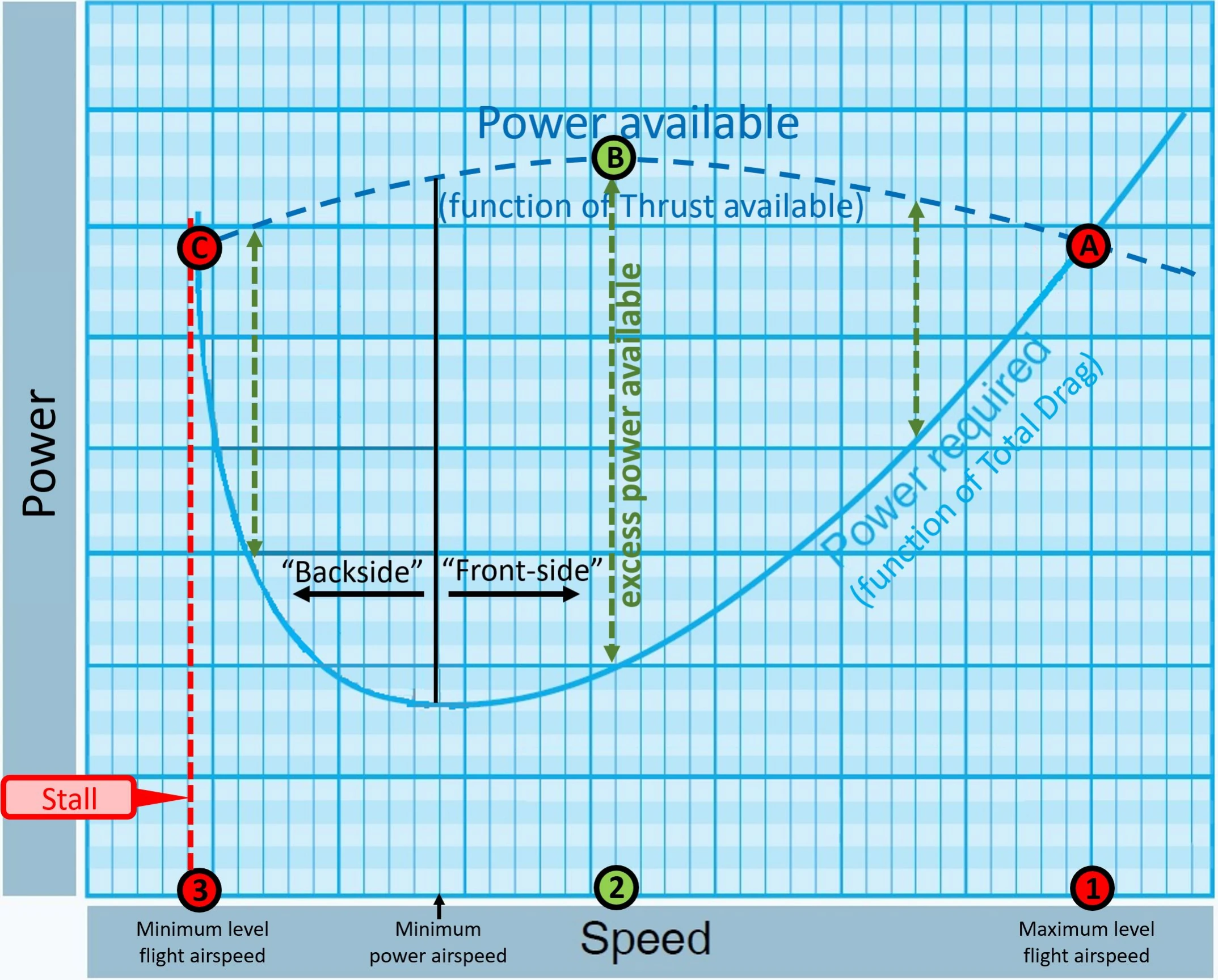
On the front side of the power required curve, where the airplane cruises at high speed (1 in Figure 4-4) and a low angle of attack (AOA) with little or no excess power or excess thrust (A in Figure 4-4), pulling back on the yoke or stick (elevator up) will result in a brief energy exchange climb, causing the airplane to slow down from 1 to 2 toward the center of the power curve [Figure 4-4]. This decrease in airspeed results in a reduction in total drag; hence available energy in the form of positive excess power (PS > 0) where thrust exceeds drag (T – D > 0). With this excess power (B in Figure 4-4) the airplane can now climb at a constant airspeed or turn in level flight while maintaining a constant airspeed at an increased load factor.
On the backside of the power required curve, where the airplane flies at low speed (3 in Figure 4-4) and high AOA with little or no excess power or excess thrust (C in Figure 4-4), pushing forward on the yoke or stick (elevator down) will result in a brief energy exchange descent, causing the airplane to accelerate from 3 to 2 toward the center of the power curve [Figure 4-4]. This increase in airspeed results in a reduction in total drag; hence available energy in the form of positive excess power (PS >0) where thrust exceeds drag (T – D > 0). With this excess power (B in Figure 4-4) the airplane can now climb at a constant airspeed or turn in level flight while maintaining a constant airspeed at an increased load factor. This role of the elevator is critical to prevent unintentional, excessive deceleration or sink rate as illustrated later in the chapter (refer to Preventing Irreversible Deceleration and/or Sink Rate section).
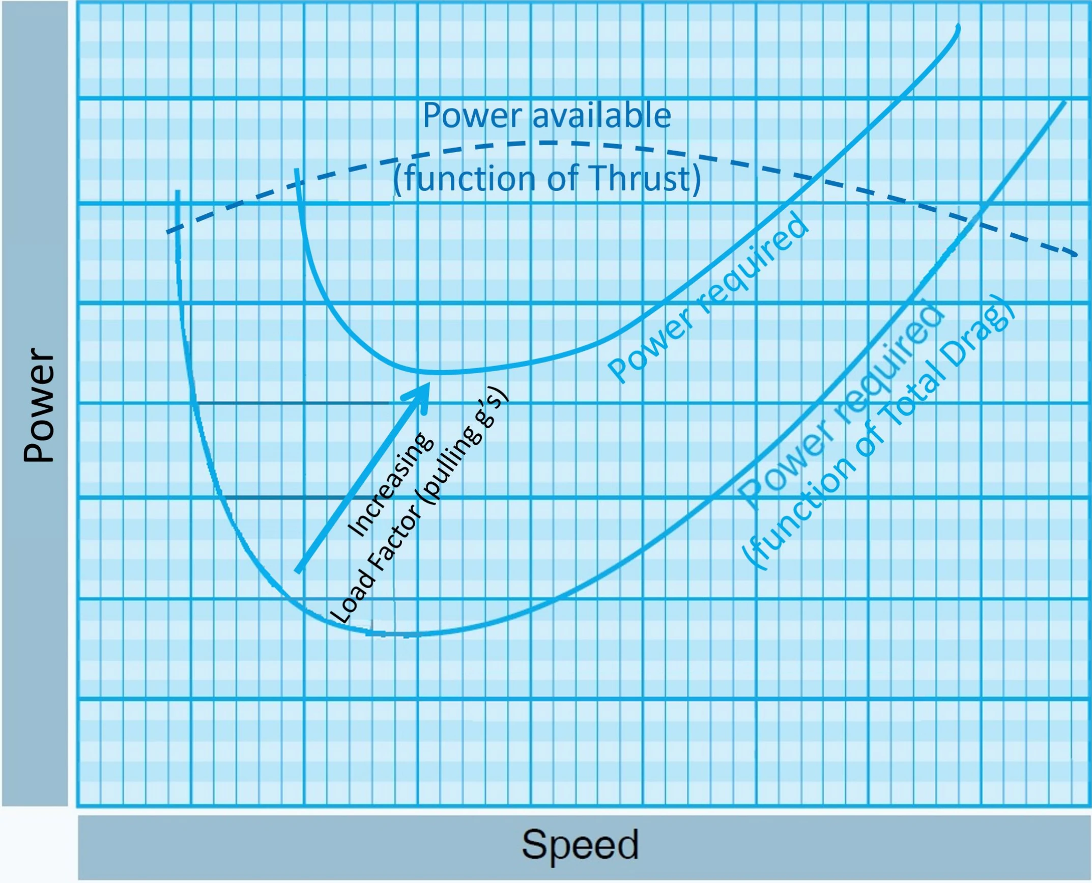
While the elevator can assist the throttle in changing T – D and PS through changes in airspeed via energy exchange as described above, occasionally the elevator can directly increase the “D” in T – D at any given speed during a level turn, thus helping the airplane rapidly bleed off total energy. As the airplane banks, load factor (lift/weight) increases because total lift has to increase to pull the airplane into the turn while simultaneously balancing its weight. This is accomplished by pulling back on the yoke (or stick) to increase AOA which results in increased induced drag and power required at any given speed. This action will quickly slow the airplane down and decrease total energy more rapidly than by just reducing the throttle setting to idle. This additional role of the elevator is shown on the power curve. [Figure 4-5]
Applying the respective role of the controls to manage the airplane’s energy state leads to a set of simple “rules” for proper throttle- elevator coordination to effectively control vertical flight path and airspeed. What are these basic rules of energy control?
Rules of Energy Control
The central principle encapsulating the role of the throttle and elevator for managing the airplane’s energy can be summed up as follows: coordinated throttle and elevator inputs control the airplane’s energy state. Modifying a popular adage, the principle can be restated as “pitch plus power controls energy state.” This central principle serves to guide a set of general energy control rules to achieve and maintain any desired vertical flight path and airspeed targets within the airplane’s energy envelope.
Visualizing the Airplane’s Ability to “Move” Between Energy States
To better understand the basic rules of energy control, a pilot needs to visualize an airplane’s energy state and its ability to switch from one energy state to another. In other words, how does an airplane “move” from an initial altitude and airspeed to any other target altitude and airspeed within its flight envelope, and how does the pilot control the process? A map should help, and in this case, it charts the status of the aircraft in terms of energy.
In a navigation map, such as an aeronautical sectional chart, the geographic position of an airplane is determined by two variables— latitude and longitude. Likewise, in an “altitude-airspeed” or “energy” map the energy position of an airplane, its energy state, is defined by two variables—altitude and airspeed. [Figure 4-6]
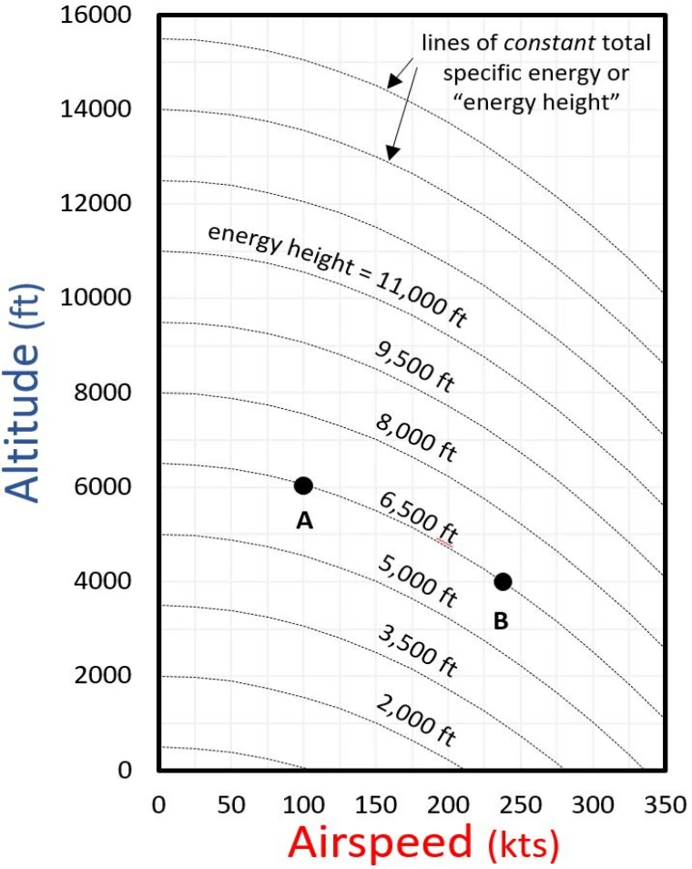
The position of an airplane in the altitude-airspeed map represents its total specific energy or ES (which is simply the sum of its potential and kinetic energies divided by aircraft weight) as determined by its current altitude and airspeed.
ES = h + V²/2g
Where,
- g = gravitational constant
- h = height (altitude)
- V = velocity (airspeed)
Since the total specific energy, ES, has the units of height (e.g., feet), it is usually called energy height. It also gets this name from the fact that energy height is the maximum height that an airplane would reach from its current altitude, if it were to trade all its speed for altitude. Figure 4-6 shows lines of constant total specific energy or energy height. Different positions of an airplane along a given energy height line have the same total energy regardless of their location on the line (e.g., A and B).
Thus, even though the airplane in point A is cruising at 100 knots and 6,000 feet, it has the same total specific energy expressed in height (6,500 feet) when cruising at 240 knots and 4,000 feet (B). This also means that the airplane in either position, A or B, would be able to “zoom” to the same maximum altitude of 6,500 feet by trading all its speed for altitude. The lines of constant energy height can be used as idealized trajectories to depict an airplane moving from one energy state to another solely through energy exchange (e.g., A to B). If the airplane rapidly exchanges altitude and airspeed, it would follow along the energy height line while, in the short term, maintaining constant total energy.